 English
 Afrikaans
 العربية
 বাংলা
বাংলা bosanski jezik
 Български
 Català
 粤语
粤语 中文(简体)
 中文(漢字)
 Hrvatski
 Čeština
 Nederlands
 Eesti keel
 Suomi
Suomi Français
 Deutsch
 Ελληνικά
 हिन्दी; हिंदी
 Magyar
 Bahasa Indonesia
 Italiano
 日本語
日本語 한국어
한국어 Latviešu valoda
 Lietuvių kalba
 македонски јазик
 Bahasa Melayu
 Norsk
Norsk پارسی
پارسی Polski
 Português
 Română
 Русский
 Cрпски језик
 Slovenčina
 Slovenščina
 Español
 Svenska
 ภาษาไทย
 Türkçe
 Українська
 اردو
اردو Tiếng Việt

প্লাস্টিক-এনক্যাপসুলেটেড চিপ পিটিসি থার্মিস্টর হল ইতিবাচক তাপমাত্রা সহগ থার্মিস্টর (পিটিসি) পৃষ্ঠ মাউন্ট প্রযুক্তি প্যাকেজ (এসএমডি) প্যাকেজিং. এগুলি সার্কিট সুরক্ষায় ব্যাপকভাবে ব্যবহৃত হয়, তাপমাত্রা সেন্সিং, এবং ক্ষুদ্রাকৃতির ইলেকট্রনিক ডিভাইস ডিজাইন. The following are their key features and selection considerations:
আমি. Core Features
Temperature Response Mechanism
At room temperature, the resistance is low (typically 1-20Ω). When the temperature exceeds the Curie point (যেমন, 105°সে), the resistance increases stepwise (কয়েক হাজার ওহম পর্যন্ত), providing self-current limiting.
The polymer matrix (পিপিটিসি) expands when overcurrent occurs, severing the conductive path and automatically recovering after the fault is resolved.
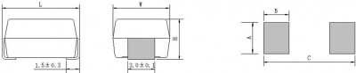
Product dimensions and recommended pad size
Packaging Advantages
Encapsulated with epoxy resin, they offer compact dimensions (যেমন, 4524 এবং 2822 packages), making them suitable for high-density PCB layouts.
They are resistant to high temperatures and humidity, meet UL94-V0 flame retardancy standards, and are suitable for lead-free reflow soldering processes. RoHS অনুগত
Suitable for lead-free wave soldering and reflow soldering of surface mount technology
Plastic encapsulated chip package, materials meet UL 94 ভি-0 flame retardancy requirements
Utilizes high-performance thermistor chip for compact size and high performance
Maintains stable performance over a long period of time
ওয়াইড অপারেটিং তাপমাত্রা পরিসীমা: -40°C to 85°C
২. Selection Parameters
| পরামিতি | সাধারণ মান/পরিসীমা | বর্ণনা |
|---|---|---|
| Zero-Power Resistor | 1-20ওহ | Initial resistance affects circuit power consumption |
| Curie Temperature | 75-250℃ | Temperature threshold for triggering protection |
| Maximum Operating Voltage | ≤250V | Must match circuit voltage level |
| Action Time | মিলিসেকেন্ড | Fast response to overcurrent or overtemperature events |
III. সাধারণ অ্যাপ্লিকেশন
Electrical instruments;
Security equipment;
যোগাযোগ সরঞ্জাম;
বাড়ির যন্ত্রপাতি;
Automotive electronics;
Other power products requiring overcurrent, ওভারভোল্টেজ, এবং ঢেউ সুরক্ষা
সার্কিট সুরক্ষা: For overcurrent protection of USB ports and battery packs.
Temperature Compensation: Linear PTC models (such as the CMZ series) simplify temperature compensation design for precision circuits.
Automotive electronics: Meets wide operating temperature range of -40°C to 200°C.
IV. Technical Comparison
| টাইপ | সুবিধা | সীমাবদ্ধতা |
|---|---|---|
| Ceramic PTC | High voltage resistance, high stability | Non-linear resistance-temperature curve |
| Polymer PPTC | স্ব-পুনরুদ্ধার, দ্রুত প্রতিক্রিয়া | Low withstand voltage (typically ≤60V) |
ভি. Mainstream Market Models
| আইটেম
Model Specifications |
Zero Power Resistance @ 25°C | Curie Temperature | Operating Current @ 25°C | Non-Operating Current @ 60°C | সর্বাধিক বর্তমান | সর্বোচ্চ ভোল্টেজ |
|
Rn(Ω) |
Tc(℃) |
এটা(এমএ) |
Ih(এমএ) |
আইম্যাক্স(ক) |
Vmax(ভি) |
|
|
SPSMD4032H450R#450 |
45 |
83±7 |
150 |
25 |
* |
450 |
|
SPSMD3225H450R#300 |
45 |
83±7 |
100 |
18 |
* |
300 |
|
SPSMD3225M450R#300 |
45 |
105±7 |
150 |
42 |
0.3 |
300 |
|
SPSMD3225M600R#300 |
60 |
105±7 |
130 |
38 |
0.3 |
300 |
|
SPSMD3225S121R#300 |
120 |
115±7 |
100 |
32 |
0.3 |
300 |
|
SPSMD3225S151R#450 |
150 |
115±7 |
95 |
28 |
0.3 |
450 |
|
SPSMD3225S251R#450 |
250 |
115±7 |
80 |
25 |
0.3 |
450 |
|
SPSMD3225S301R#450 |
300 |
115±7 |
70 |
20 |
0.3 |
450 |
|
SPSMD3225S501R#450 |
500 |
115±7 |
55 |
15 |
0.3 |
450 |
|
SPSMD40325S600R#420 |
60 |
115±7 |
160 |
45 |
0.8 |
420 |
|
SPSMD4032S800R#450 |
80 |
115±7 |
140 |
40 |
0.8 |
450 |
|
SPSMD4032S101R#450 |
100 |
115±7 |
120 |
35 |
0.8 |
450 |
|
SPSMD4032S151R#450 |
150 |
115±7 |
100 |
30 |
0.8 |
450 |
|
SPSMD4032S301R#450 |
300 |
115±7 |
80 |
25 |
0.8 |
450 |
|
SPSMD4032S501R#450 |
500 |
115±7 |
65 |
18 |
0.8 |
450 |
|
SPSMD3225H102R#550 |
1000 |
83±7 |
25 |
5 |
0.1 |
550 |
|
SPSMD3225H152R#650 |
1500 |
83±7 |
25 |
4 |
0.1 |
650 |
|
SPSMD3225H202R#650 |
2000 |
83±7 |
25 |
3 |
0.1 |
650 |
*SPSMD4032H450R#450 和SPSMD3225H450R#300 分别可用于 485 通讯接口保护抗 380VAC 和 220VAC。
JK-EK Series: 4524/2822 package, CQC/UL certified, suitable for LEDs and industrial equipment.
CMZL Series: Linear PTC, with controllable resistance-temperature gradient (±2000ppm/°C), suitable for automotive and medical applications.
Plastic-encapsulated chip PTC thermistors balance protection performance and space efficiency through an integrated design, making them an ideal solution for compact electronic devices.
VI. সতর্কতা
General
To ensure the reliability of chip thermistors in actual use, extreme operating conditions should be considered during the design phase, and a certain margin should be allowed. Operating Environment
পরিবেষ্টিত তাপমাত্রা: -40-125°সে
Relative Humidity: ≤95%
Atmospheric Pressure: 86-106 kPa
Vibration Frequency: 10-50 Hz
Acceleration: 98 m/s²
Storage
The chip thermistor should be stored in its original packaging. Do not open the packaging for storage.
Original Packaging Storage Conditions: Storage Temperature -25°C to +45°C, Annual Average Relative Humidity ≤75%, Maximum Not Exceeding 95%.
For chip thermistors, avoid contamination of the thermistor terminal surfaces during storage, handling, and processing.
SMD thermistors should be stored in environments that could affect their performance.
Use the chip thermistor within one year of receipt. After this time, recheck the solderability of the electrodes.
Transportation
The thermistor should be protected from dropping and impact during transportation.
It is recommended to wear gloves when handling the thermistor.
For chip thermistors, avoid contamination of the thermistor solder terminals during transportation.
Soldering (where applicable)
Sn96.5Ag3.0Cu0.5 solder paste is recommended.
Insufficient preheating may cause cracks in the thermistor ceramic chip.
The recommended maximum soldering temperature is 255±5°C for 3-6 সেকেন্ড. Excessive soldering temperatures and extended soldering times may damage the thermistor.
Rapid cooling by immersion in solvent is not recommended.
After soldering, it is recommended to completely remove the flux or use a no-clean flux.