 English
 Afrikaans
 العربية
 বাংলা
বাংলা bosanski jezik
 Български
 Català
 粤语
粤语 中文(简体)
 中文(漢字)
 Hrvatski
 Čeština
 Nederlands
 Eesti keel
 Suomi
Suomi Français
 Deutsch
 Ελληνικά
 हिन्दी; हिंदी
 Magyar
 Bahasa Indonesia
 Italiano
 日本語
日本語 한국어
한국어 Latviešu valoda
 Lietuvių kalba
 македонски јазик
 Bahasa Melayu
 Norsk
Norsk پارسی
پارسی Polski
 Português
 Română
 Русский
 Cрпски језик
 Slovenčina
 Slovenščina
 Español
 Svenska
 ภาษาไทย
 Türkçe
 Українська
 اردو
اردو Tiếng Việt
We offer a wide range of the best 1-Wire DS18B20 sensor connectors, including Nanoflex, DisplayPort, USB, Solar, SATA, HDMI, ATA IDE, SAS & many more. All cables are manufactured to the highest industry standards. Using Sensor Circuit Assembly for box builds allows you to focus on your design and marketing, reduce costs, and reap the benefits of our assembly lines, QA processes, and manufacturing expertise.
DS18B20-sensoren kommuniserer ved hjelp av “1-Metalltråd” protokoll, som betyr at den bruker en enkelt datalinje for all kommunikasjon med en mikrokontroller, slik at flere sensorer kan kobles til på samme linje og identifiseres med deres unike 64-bits seriekode; denne enkelt datalinjen trekkes høyt med en motstand og sensoren overfører data ved å trekke linjen lavt i spesifikke tidsluker for å sende informasjonsbiter.
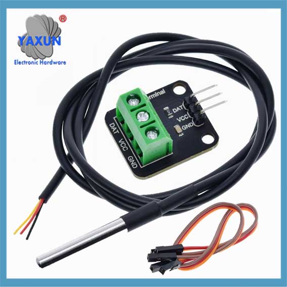
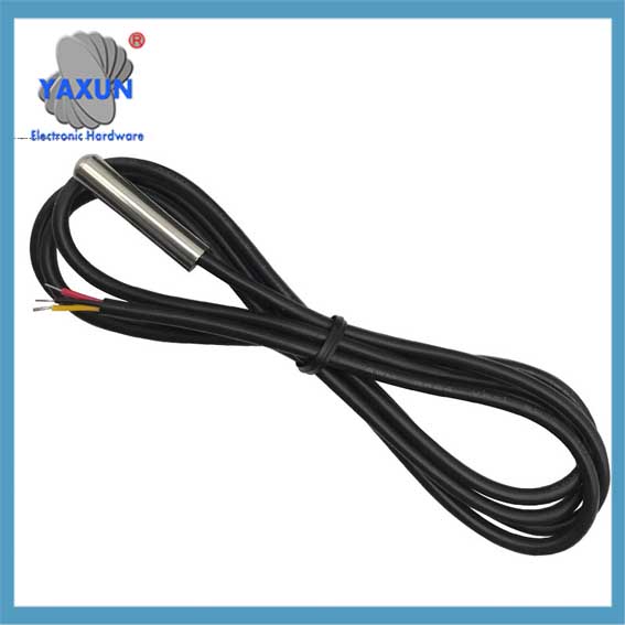
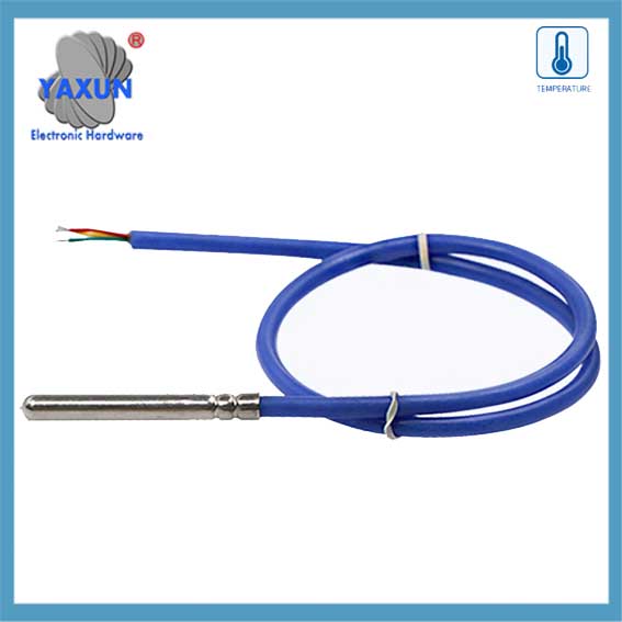
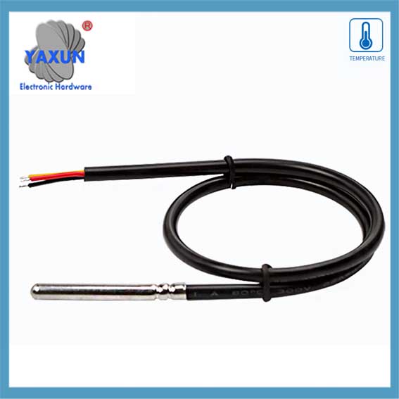
DS18B20 temperatursensor: The DS18B20 waterproof probe is designed for underwater use, capable of operating in wet or moist environments without being damaged by water or moisture.
Temperature sensor supply voltage: 3.0V ~ 5.25V;
Driftstemperaturområde:-55 ℃ til +125 ℃ (-67 ℉ to +257 ℉);
Provides from 9-bit to 12-bit Celsius temperature measurements;
Adapter module is equipped with a pull-up resistor, and directly connects to the GPIO of the Raspberry Pi without an external resistor;
Use this adapter module kit to simplify connecting the waterproof temperature sensor to your project.
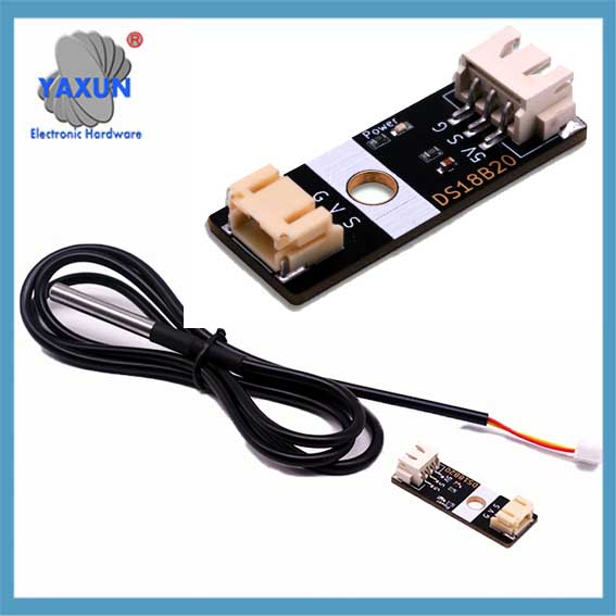 DS18B20 digital temperaturfølersonde & XH2.54 to PH2.0 module |
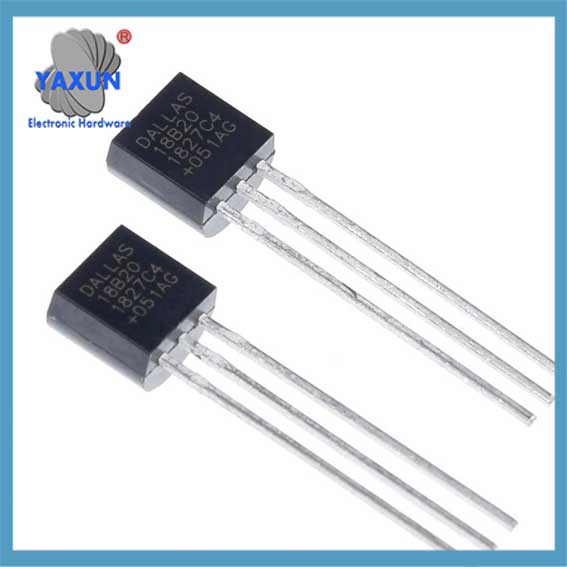 China-made DS18B20 chip temperature acquisition TO-92 temperature sensor |
 DS18B20 temperatursensor 1-leder vanntett kabel + adapterkortsett |
1. Key points about the 1-Wire protocol:
Single data line:
Only one wire is needed for communication between the sensor and the microcontroller.
Half-duplex communication:
Data can be sent in both directions, but only one direction at a time.
Parasite power:
The DS18B20 can be powered directly from the data line during communication, eliminating the need for a separate power supply in some cases.
Unique device addresses:
Each DS18B20 sensor has a unique 64-bit serial code that allows the microcontroller to identify and address individual sensors on the bus.
Communication steps with a DS18B20:
1.1 Reset pulse:
The microcontroller initiates communication by pulling the data line low for a specific duration (tilbakestille puls).
1.2 Presence pulse:
If a DS18B20 is present on the bus, it will respond with a short pulse, indicating its presence.
1.3 ROM kommando:
The microcontroller sends a ROM command to either read the unique 64-bit code of a specific sensor (“Match ROM”) or to address all sensors on the bus (“Skip ROM”).
1.4 Function command:
Depending on the desired operation (like reading temperature), the microcontroller sends a specific function command to the sensor.
1.5 Data transfer:
Data is transmitted bit-by-bit, with the sensor pulling the data line low to send a ‘0’ and letting the line go high to send a ‘1’.
2. Detaljert forklaring av DS18B20s 1-Wire kommunikasjonsprotokoll
Årsaken til at DS18B20 -sensorer er mye brukt skyldes i stor grad den unike kommunikasjonsprotokollen – 1-Ledningskommunikasjonsprotokoll. Denne protokollen forenkler kravene til maskinvareforbindelser og gir en effektiv måte å overføre data. Dette kapittelet vil dypt analysere arbeidsmekanismen og datautvekslingsprosessen for 1-linjers kommunikasjonsprotokoll for å legge et solid grunnlag for påfølgende programmeringspraksis.
2.1 Grunnleggende om 1-tråds kommunikasjonsprotokoll
2.1.1 Funksjoner i 1-tråds kommunikasjonsprotokoll:
DS18B20 1-tråd kommunikasjonsprotokoll kalles også “enkeltbuss” teknologi. Den har følgende funksjoner: – Enkeltbusskommunikasjon: Bare en datalinje brukes til toveis dataoverføring, Noe som reduserer kompleksiteten i ledningene sammenlignet med den tradisjonelle kommunikasjonsmetoden for flere trådføler. – Forbindelse med flere enheter: Støtter tilkobling av flere enheter på en databuss, og identifiserer og kommuniserer gjennom enhetens identifikasjonskoder. – Lavt strømforbruk: Under kommunikasjon, enheten kan være i en lav effekt standby-tilstand når du ikke deltar i kommunikasjon. – Høy presisjon: Med en kortere dataoverføringstid, Det kan redusere ekstern interferens og forbedre datatøyaktigheten.
2.1.2 Dataformat og timinganalyse av 1-tråds kommunikasjon
Dataformatet til 1-Wire Communication Protocol følger en spesifikk tidsregel. Det inkluderer initialiseringstiming, Skriv timing og les timing:
Initialiseringstiming: Verten starter først tilstedeværelsesdeteksjonstimingen (Tilstedeværelsespuls) ved å trekke ned bussen i en viss periode, og sensoren sender deretter en tilstedeværelsespuls som svar.
Skriv timing: Når verten sender en skrivetidspunkt, Den trekker først bussen i omtrent 1-15 mikrosekunder, slipper deretter bussen, og sensoren trekker ned bussen i 60-120 Mikrosekunder for å svare.
Les timing: Verten varsler sensoren om å sende data ved å trekke ned bussen og slippe den, og sensoren vil sende ut databiten på bussen etter en viss forsinkelse.
 Analog Devices DS18B20+, MAXIM Programmable Resolution 1-Wire Digital Thermometer |
 DS18B20 12-bit 1-Wire Digital Temperature Sensor w/ 1 Meter Cable |
 DS18B20 sensor probe dedicated to temperature and humidity collection in cold chain cold storage |
2.2 Software implementation of data communication
2.2.1 Initialization and reset of 1-line communication
At the software level, initialization and reset of 1-Wire communication is the first step of communication. The following is the pseudo code to implement this process:
// OneWire communication initialization function
void OneWire_Init() {
// Set the bus to input mode and enable the pull-up resistor
SetPinMode(DS18B20_PIN, INPUT_PULLUP);
// Wait for the bus to be idle
DelayMicroseconds(1);
// Send a reset pulse
OneWire_Reset();
}
// OneWire communication reset function
void OneWire_Reset() {
// Pull down the bus
SetPinMode(DS18B20_PIN, OUTPUT_LOW);
DelayMicroseconds(480);
// Release the bus
SetPinMode(DS18B20_PIN, INPUT_PULLUP);
DelayMicroseconds(70);
// Wait for the presence of a pulse
hvis (!WaitForOneWirePresence())
// No pulse was detected, maybe the sensor is not connected or the initialization failed
HandleError();
DelayMicroseconds(410);
}
// Waiting for the presence of a pulse
bool WaitForOneWirePresence() {
return ReadPin(DS18B20_PIN) == 0; // Assume low level is a signal presence
}
2.2.2 Data reading and writing operations
Data reading and writing operations are the core part of sensor communication. The following code shows how to write a byte to a one-wire bus:
// Write a byte to a one-wire bus
void OneWire_WriteByte(byte data) {
til (int i = 0; jeg < 8; i++) {
OneWire_WriteBit(data & 0x01);
data >>= 1;
}
}
// Write a bit to a one-wire bus
void OneWire_WriteBit(bit data) {
SetPinMode(DS18B20_PIN, OUTPUT_LOW);
hvis (data) {
// Release the bus when writing 1
SetPinMode(DS18B20_PIN, INPUT_PULLUP);
DelayMicroseconds(1);
} ellers {
// Continue to pull the bus low when writing 0
DelayMicroseconds(60);
}
SetPinMode(DS18B20_PIN, INPUT_PULLUP);
DelayMicroseconds(1);
}
Next is the function to read a byte:
// Read a byte from the one-wire bus
byte OneWire_ReadByte() {
byte data = 0;
til (int i = 0; jeg < 8; i++) {
data >>= 1;
hvis (OneWire_ReadBit())
data |= 0x80;
}
returnere data;
}
// Read a bit from the one-wire bus
bit OneWire_ReadBit() {
SetPinMode(DS18B20_PIN, OUTPUT_LOW);
SetPinMode(DS18B20_PIN, INPUT_PULLUP);
DelayMicroseconds(3);
bool result = ReadPin(DS18B20_PIN);
DelayMicroseconds(57);
return result;
}
2.2.3 Verification mechanism of OneWire communication
The OneWire communication protocol uses a simple verification mechanism in the data exchange process, usually by reading back the written data to verify the correctness of the data. The following is a sample code for verifying the written data:
byte data = 0x55; // Assume that the data to be sent
OneWire_WriteByte(data); // Write data to the OneWire bus
byte readData = OneWire_ReadByte(); // Read back data from the OneWire bus
hvis (readData != data) {
HandleError(); // If the read-back data does not match the written data, handle the error