 English
 Afrikaans
 العربية
 বাংলা
বাংলা bosanski jezik
 Български
 Català
 粤语
粤语 中文(简体)
 中文(漢字)
 Hrvatski
 Čeština
 Nederlands
 Eesti keel
 Suomi
Suomi Français
 Deutsch
 Ελληνικά
 हिन्दी; हिंदी
 Magyar
 Bahasa Indonesia
 Italiano
 日本語
日本語 한국어
한국어 Latviešu valoda
 Lietuvių kalba
 македонски јазик
 Bahasa Melayu
 Norsk
Norsk پارسی
پارسی Polski
 Português
 Română
 Русский
 Cрпски језик
 Slovenčina
 Slovenščina
 Español
 Svenska
 ภาษาไทย
 Türkçe
 Українська
 اردو
اردو Tiếng Việt
PT100 arba PT1000 jutiklio zondo temperatūros matavimo grandinė paprastai susideda iš stabilaus srovės šaltinio, kuris sužadina jutiklį, didelio tikslumo varžos matavimo grandinė, skirta aptikti varžos pokyčius priklausomai nuo temperatūros, ir analoginis-skaitmeninis keitiklis (ADC) išmatuotą įtampą paversti skaitmeniniu signalu, kuris gali būti apdorotas mikrovaldikliu arba duomenų rinkimo sistema; pagrindinis skirtumas tarp PT100 ir PT1000 grandinių yra pasipriešinimo verčių skalė dėl to, kad Pt100 vardinė varža 100 omų esant 0 °C, o Pt1000 turi 1000 omai 0 ° C., dažnai reikia koreguoti matavimo grandinę, priklausomai nuo pageidaujamo tikslumo ir taikymo.
Straipsnyje pristatomas metalinių šiluminių rezistorių jutiklių PT100 ir PT1000 varžos pokytis esant skirtingoms temperatūroms, taip pat įvairūs temperatūros matavimo grandinės sprendimai. Įskaitant varžos įtampos padalijimą, tilto matavimas, nuolatinės srovės šaltinis ir AD623, AD620 gavimo grandinė. Siekiant atsispirti trukdžiams, ypač elektromagnetiniai trukdžiai aviacijos erdvėje, siūloma oro PT1000 temperatūros jutiklio gavimo grandinės konstrukcija, įskaitant T tipo filtrą, skirtą filtruoti ir pagerinti matavimo tikslumą.
Santrauka, sukurta CSDN naudojant išmaniąją technologiją
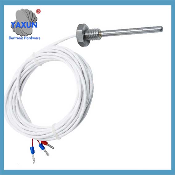
 PT100 Temperatūros kabelio jutiklis skirtas tiksliam temperatūros matavimui konteineriuose, cisternos ir vamzdžiai |
 Temperatūros jutiklio zondo T100 aukštos temperatūros -50~260 kabelis |
 PT100 platinos atsparumo temperatūros jutiklis siųstuvo paviršiaus temperatūrai |
PT100/PT1000 temperatūros matavimo grandinės sprendimas
1. PT100 ir PT1000 jutiklių temperatūros varžos keitimo lentelė
Metaliniai šiluminiai rezistoriai, tokie kaip nikelis, vario ir platinos rezistoriai turi teigiamą koreliaciją su temperatūros pokyčiu. Platina turi stabiliausias fizines ir chemines savybes ir yra plačiausiai naudojama. Dažniausiai naudojamų platinos atsparumo Pt100 jutiklių zondų temperatūros matavimo diapazonas yra -200~850 ℃, ir temperatūros matavimo diapazonai Pt500, Pt1000 jutiklio zondai, ir tt. nuosekliai mažinami. 1000 Pt, temperatūros matavimo diapazonas yra -200 ~ 420 ℃. Pagal IEC751 tarptautinį standartą, platininio rezistoriaus Pt1000 temperatūros charakteristikos atitinka šiuos reikalavimus:
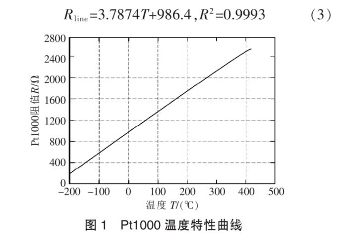
Pt1000 temperatūros charakteristikos kreivė
Pagal Pt1000 temperatūros charakteristikų kreivę, varžos charakteristikos kreivės nuolydis šiek tiek pakinta normalios darbinės temperatūros diapazone (kaip parodyta paveiksle 1). Apytikslį atsparumo ir temperatūros ryšį galima gauti naudojant linijinį montavimą:
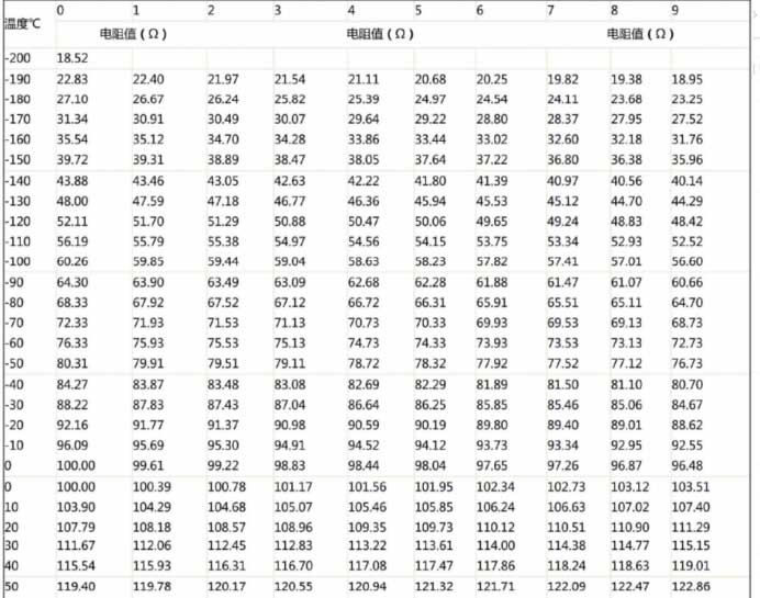
PT100 temperatūros atsparumo keitimo lentelė 1
2. Dažniausiai naudojami gavimo grandinių sprendimai
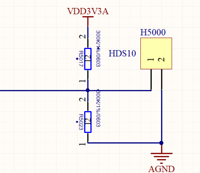
2. 1 Rezistoriaus įtampos daliklio išvestis 0~3,3V/3V analoginės įtampos vieno lusto AD prievado tiesioginis gavimas
Temperatūros matavimo grandinės įtampos išvesties diapazonas yra 0–3,3 V, PT1000 (PT1000 atsparumo vertė labai pasikeičia, ir temperatūros matavimo jautrumas yra didesnis nei PT100; PT100 labiau tinka didelio masto temperatūros matavimams).
Paprasčiausias būdas yra naudoti įtampos padalijimo metodą. Įtampą generuoja TL431 įtampos atskaitos šaltinio lustas, kuris yra 4 V įtampos atskaitos šaltinis. Arba, REF3140 gali būti naudojamas generuoti 4,096 V kaip atskaitos šaltinį. Referencinio šaltinio lustuose taip pat yra REF3120, 3125, 3130, 3133, ir 3140. Lustas naudoja SOT-32 paketą ir 5 V įvesties įtampą. Išėjimo įtampą galima pasirinkti pagal reikiamą atskaitos įtampą. Žinoma, pagal įprastą mikrovaldiklio AD prievado įtampos įvesties diapazoną, ji negali viršyti 3V/3,3V.
PT100 vieno lusto AD prievado grandinės tiesioginis įsigijimas
2.2 Rezistoriaus įtampos padalijimo išėjimas 0~5V analoginė įtampa, o mikrovaldiklio AD prievadas jį tiesiogiai surenka.
Žinoma, kai kurios grandinės maitinamos 5 V mikrovaldikliu, o maksimali PT1000 darbinė srovė yra 0,5 mA, todėl normaliam komponento veikimui užtikrinti turi būti naudojama atitinkama varžos vertė.
Pavyzdžiui, 3,3 V įtampos padalijimo schemoje aukščiau pakeičiama 5 V. To pranašumas yra tas, kad 5 V įtampos padalijimas yra jautresnis nei 3,3 V įtampa, ir rinkimas tikslesnis. Prisimink, teorinė skaičiuojama išėjimo įtampa negali viršyti +5V. Priešingu atveju, bus sugadintas mikrovaldiklis.
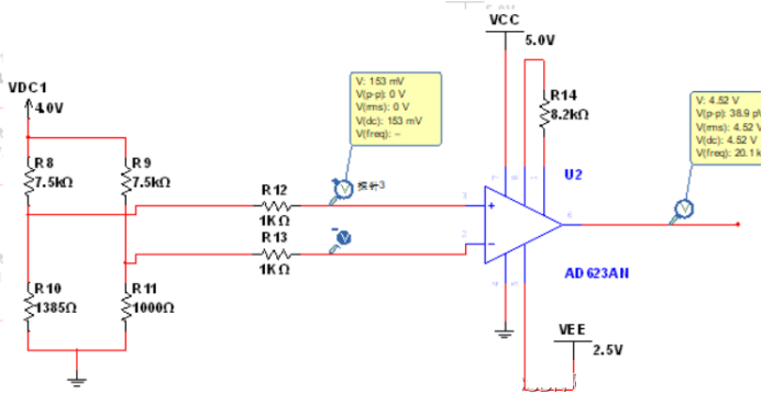
2.3 Dažniausiai naudojamas tilto matavimas

PT100 įtampos daliklio grandinė išveda 0–5 V analoginę įtampą
Naudokite R11, R12, R13 ir Pt1000, kad sudarytų matavimo tiltelį, kur R11=R13=10k, R12=1000R tikslumo rezistorius. Kai Pt1000 varžos vertė nėra lygi R12 varžos vertei, tiltas išduos mV lygio įtampos skirtumo signalą. Šį įtampos skirtumo signalą sustiprina prietaiso stiprintuvo grandinė ir išvedamas norimas įtampos signalas, kurį galima tiesiogiai prijungti prie AD konvertavimo lusto arba mikrovaldiklio AD prievado.
Šios grandinės varžos matavimo principas:
1) PT1000 yra termistorius, o jo varža kinta iš esmės tiesiškai kintant temperatūrai.
2) At 0 laipsnių, PT1000 varža yra 1kΩ, tada Ub ir Ua yra lygūs, tai yra, Uba = Ub – Daryk = 0.
3) Darant prielaidą, kad esant tam tikrai temperatūrai, PT1000 varža yra 1,5 kΩ, tada Ub ir Ua nėra lygūs. Pagal įtampos daliklio principą, galime rasti Uba = Ub – Daryk > 0.
4) OP07 yra operacinis stiprintuvas, o jo įtampos stiprinimo koeficientas A priklauso nuo išorinės grandinės, kur A = R2/R1 = 17.5.
5) OP07 išėjimo įtampa Uo = Uba * A. Taigi, jei naudosime voltmetrą OP07 išėjimo įtampai matuoti, galime daryti išvadą apie Uab vertę. Kadangi Ua yra žinoma reikšmė, galime toliau apskaičiuoti Ub reikšmę. Tada, naudojant įtampos daliklio principą, galime apskaičiuoti specifinę PT1000 varžos vertę. Šis procesas gali būti atliktas naudojant programinės įrangos skaičiavimus.
6) Jei žinome PT1000 varžos vertę bet kurioje temperatūroje, mums tereikia ieškoti lentelės pagal varžos vertę, kad sužinotume esamą temperatūrą.
2.4 Nuolatinis srovės šaltinis
Dėl savaime įkaistančio terminio rezistoriaus efekto, būtina užtikrinti, kad per rezistorių tekanti srovė būtų kuo mažesnė, ir paprastai tikimasi, kad srovė bus mažesnė nei 10 mA. Patikrinta, kad platinos rezistorius PT100 savaime įkaista 1 mW sukels temperatūros pokytį 0.02 iki 0,75 ℃, todėl sumažinus platininio rezistoriaus PT100 srovę, galima sumažinti ir jo temperatūros pokytį. Tačiau, jei srovė per maža, jis jautrus triukšmo trukdžiams, todėl paprastai imamasi 0.5 į 2 Ma, todėl nuolatinės srovės šaltinio srovė pasirenkama kaip 1mA nuolatinės srovės šaltinis.
Pasirinktas lustas yra nuolatinės įtampos šaltinio lustas TL431, o tada dabartinis neigiamas grįžtamasis ryšys naudojamas paversti jį nuolatinės srovės šaltiniu. Grandinė parodyta paveikslėlyje:
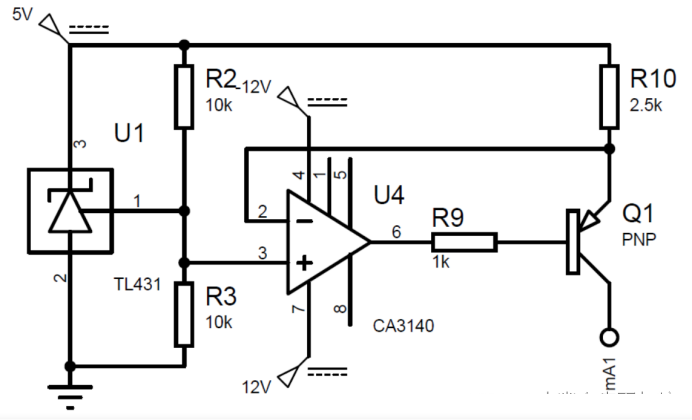
Rezistoriaus PT100 grandinės gavimo schemos nuolatinės srovės šaltinis
Operacinis stiprintuvas CA3140 naudojamas siekiant pagerinti srovės šaltinio apkrovą, o išėjimo srovės skaičiavimo formulė yra:
Įterpti paveikslėlio aprašymą čia Rezistorius turi būti a 0.1% tikslumo rezistorius. Galutinė išėjimo srovė yra 0,996 mA, tai yra, tikslumas yra 0.4%.
Nuolatinės srovės šaltinio grandinė turi turėti šias charakteristikas:
Temperatūros stabilumas: Kadangi mūsų temperatūros matavimo aplinka yra 0-100 ℃, srovės šaltinio išėjimas neturėtų būti jautrus temperatūrai. O TL431 pasižymi itin žemu temperatūros koeficientu ir žemu temperatūrų dreifu.
Geras apkrovos reguliavimas: Jei srovės bangavimas yra per didelis, tai sukels skaitymo klaidas. Pagal teorinę analizę. Kadangi įėjimo įtampa svyruoja tarp 100-138,5 mV, ir temperatūros matavimo diapazonas yra 0-100 ℃, temperatūros matavimo tikslumas yra ±1 laipsnis Celsijaus, todėl išėjimo įtampa turėtų pasikeisti 38,5/100 = 0,385 mV kas 1 ℃ aplinkos temperatūrai padidėjus. Siekiant užtikrinti, kad srovės svyravimai neturėtų įtakos tikslumui, apsvarstykite patį ekstremaliausią atvejį, adresu 100 laipsniai Celsijaus, PT100 varžos vertė turėtų būti 138,5R. Tada srovės pulsacija turėtų būti mažesnė nei 0,385/138,5 = 0,000278 mA, tai yra, srovės pokytis keičiant apkrovą turi būti mažesnis nei 0,000278 mA. Realiame modeliavime, dabartinis šaltinis iš esmės išlieka nepakitęs.
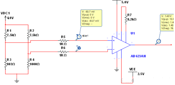
3. AD623 gavimo grandinės sprendimas
Principas gali būti susijęs su aukščiau nurodytu tilto matavimo principu.
Žemos temperatūros gavimas:
AD620 matuoja PT100 gavimo tirpalo aukštą temperatūrą (150°)
Aukštos temperatūros gavimas
Čia įterpkite nuotraukos aprašymą
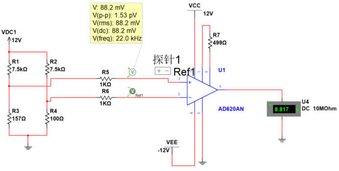
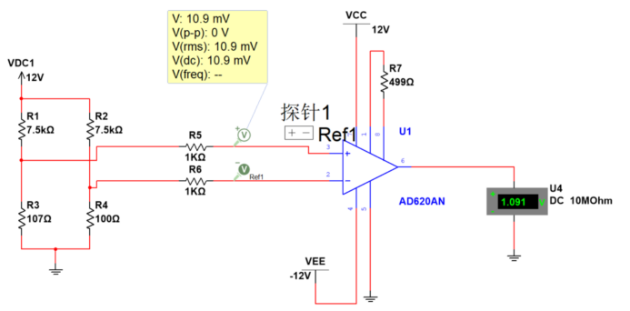
4. AD620 gavimo grandinės sprendimas
AD620 PT100 gavimo tirpalas aukštai temperatūrai (150°):

AD620 matuoja PT100 gavimo tirpalą žemoje temperatūroje (-40°)
AD620 PT100 gavimo tirpalas žemai temperatūrai (-40°):
AD620 matuoja PT100 gavimo schemą kambario temperatūroje (20°)
AD620 PT100 gavimo tirpalas kambario temperatūrai (20°):
PT100 jutiklio aukštos temperatūros gavimo grandinė
5. PT100 ir PT1000 jutiklių antiinterferencinė filtravimo analizė
Temperatūros matavimas tam tikrame komplekse, atšiaurioje ar specialioje aplinkoje bus dideli trukdžiai, daugiausia įskaitant EMI ir REI. Pavyzdžiui, taikant variklio temperatūros matavimą, aukšto dažnio trikdžiai, atsirandantys dėl variklio valdymo ir didelio variklio sukimosi greičio.
Taip pat yra daug temperatūros kontrolės scenarijų aviacijos ir kosmoso transporto priemonėse, kurios matuoja ir valdo elektros ir aplinkos kontrolės sistemą. Temperatūros valdymo pagrindas yra temperatūros matavimas. Kadangi termistoriaus varža gali keistis tiesiškai priklausomai nuo temperatūros, Platinos atsparumo naudojimas temperatūrai matuoti yra efektyvus didelio tikslumo temperatūros matavimo metodas. Pagrindinės problemos yra tokios:
1. Švino laido varža lengvai įvedama, taip paveikdamas jutiklio matavimo tikslumą;
2. Tam tikroje stiprių elektromagnetinių trukdžių aplinkoje, trikdžiai gali būti paversti nuolatinės srovės išėjimo poslinkio klaida, kai juos ištaiso instrumento stiprintuvas, turinčios įtakos matavimo tikslumui.
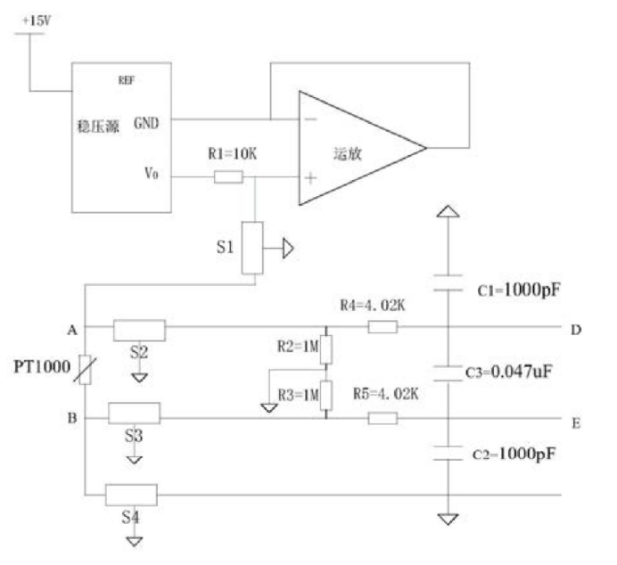
5.1 Oro erdvėlaivio PT1000 gavimo grandinė
Dėl antielektromagnetinių trukdžių tam tikroje aviacijoje žr. orlaivių PT1000 gavimo grandinės konstrukciją..
PT100 jutiklio AD623 gavimo grandinės schema
Filtras yra nustatytas atokiausiame gavimo grandinės gale. PT1000 gavimo išankstinio apdorojimo grandinė yra tinkama orlaivių elektroninės įrangos sąsajų išankstiniam anti-elektromagnetinių trukdžių apdorojimui.; konkreti grandinė yra:
+15V įėjimo įtampa per įtampos reguliatorių paverčiama +5V didelio tikslumo įtampos šaltiniu. +5V didelio tikslumo įtampos šaltinis yra tiesiogiai prijungtas prie rezistoriaus R1, o kitas rezistoriaus R1 galas padalintas į du kelius. Vienas yra prijungtas prie operacinės stiprintuvo fazės įvesties galo, o kitas yra prijungtas prie PT1000 rezistoriaus A galo per T tipo filtrą S1. Operatyvinio stiprintuvo išėjimas yra prijungtas prie invertuojančios įvesties, kad susidarytų įtampos sekiklis, ir invertuojantis įėjimas yra prijungtas prie įtampos reguliatoriaus įžeminimo prievado, kad būtų užtikrinta, jog įtampa fazės įėjime visada būtų lygi nuliui. Praleidus S2 filtrą, vienas PT1000 rezistoriaus galas A padalintas į du kelius, vienas per rezistorių R4 kaip diferencinės įtampos įvestį D, ir vienas per rezistorių R2 į AGND. Praleidus S3 filtrą, kitas PT1000 rezistoriaus galas B yra padalintas į du kelius, vienas per rezistorių R5 kaip diferencinės įtampos įvestis E, ir vienas per rezistorių R3 į AGND. D ir E yra sujungti per kondensatorių C3, D yra prijungtas prie AGND per kondensatorių C1, ir E yra prijungtas prie AGND per kondensatorių C2. Tikslią PT1000 varžos vertę galima apskaičiuoti išmatuojant skirtingą įtampą tarp D ir E.
+15V įėjimo įtampa per įtampos reguliatorių paverčiama +5V didelio tikslumo įtampos šaltiniu. +5V yra tiesiogiai prijungtas prie R1. Kitas R1 galas yra padalintas į du kelius, vienas prijungtas prie operatyvinio stiprintuvo fazės įvesties, o kitas prijungtas prie PT1000 rezistoriaus A galo per T tipo filtrą S1. Operatyvinio stiprintuvo išėjimas yra prijungtas prie invertuojančios įvesties, kad susidarytų įtampos sekiklis, ir invertuojantis įėjimas yra prijungtas prie įtampos reguliatoriaus įžeminimo prievado, kad būtų užtikrinta, jog įtampa invertuojamajame įėjime visada būtų lygi nuliui. Šiuo metu, srovė, tekanti per R1, yra pastovi 0,5 mA. Įtampos reguliatorius naudoja AD586TQ/883B, o operacinės sistemos stiprintuvas naudoja OP467A.
Praleidus S2 filtrą, vienas PT1000 rezistoriaus galas A padalintas į du kelius, vienas per rezistorių R4 kaip diferencinės įtampos įvesties galas D, ir vienas per rezistorių R2 į AGND. Praleidus S3 filtrą, kitas PT1000 rezistoriaus galas B yra padalintas į du kelius, vienas per rezistorių R5 kaip diferencinės įtampos įvesties galas E, ir vienas per rezistorių R3 į AGND. D ir E yra sujungti per kondensatorių C3, D yra prijungtas prie AGND per kondensatorių C1, ir E yra prijungtas prie AGND per kondensatorių C2.
R4 ir R5 varža yra 4,02k omų, R1 ir R2 varža yra 1M omų, C1 ir C2 talpa yra 1000pF, o C3 talpa yra 0,047 uF. R4, R5, C1, C2, ir C3 kartu sudaro RFI filtrų tinklą. RFI filtras užbaigia įvesties signalo žemųjų dažnių filtravimą, ir išfiltruoti objektai apima diferencinio režimo trikdžius ir bendrojo režimo trikdžius, perduodamus įvesties diferencialiniame signale. Įvesties signale perduodamų bendrojo režimo trukdžių ir diferencinio režimo trukdžių –3dB ribinio dažnio apskaičiavimas parodytas formulėje:
Oro erdvėlaivio PT1000 gavimo grandinė
Atsparumo vertės pakeitimas skaičiavime, bendrojo režimo ribinis dažnis yra 40 kHz, ir diferencinio režimo ribinis dažnis yra 2,6 KHZ.
Pabaigos taškas B yra prijungtas prie AGND per S4 filtrą. Tarp jų, visi filtro įžeminimo gnybtai nuo S1 iki S4 yra prijungti prie orlaivio ekranavimo įžeminimo. Kadangi srovė, tekanti per PT1000, yra žinoma 0,05 mA, tikslią PT1000 varžos vertę galima apskaičiuoti išmatuojant skirtingą įtampą abiejuose D ir E galuose.
Nuo S1 iki S4 naudojami T tipo filtrai, modelis GTL2012X-103T801, su ribiniu dažniu M±20 %. Ši grandinė įveda žemųjų dažnių filtrus į išorinės sąsajos linijas ir atlieka RFI filtravimą pagal diferencinę įtampą. Kaip PT1000 išankstinio apdorojimo grandinė, efektyviai pašalina elektromagnetinius ir RFI spinduliuotės trukdžius, o tai labai pagerina surinktų vertybių patikimumą. Be to, įtampa tiesiogiai matuojama iš abiejų PT1000 rezistoriaus galų, pašalinant laidų pasipriešinimo sukeltą klaidą ir pagerinant varžos vertės tikslumą.
 3-laidas B klasės aukštos pramoninės temperatūros valdymo PT100 platinos šiluminio rezistoriaus temperatūros jutiklis |
 K-E tipo suspaudimo spyruoklinė termopora, pt100 temperatūros jutiklio zondas |
 Didelio tikslumo PT100 temperatūros jutiklis transformatoriaus temperatūros matavimui |
5.2 T tipo filtras
Čia įterpkite nuotraukos aprašymą
T tipo filtras susideda iš dviejų induktorių ir kondensatorių. Abu jo galai turi didelę varžą, ir jo įterpimo nuostolių efektyvumas yra panašus į π tipo filtro, bet tai nėra linkusi “skambėjimas” ir gali būti naudojamas perjungimo grandinėse.