 English
 Afrikaans
 العربية
 বাংলা
বাংলা bosanski jezik
 Български
 Català
 粤语
粤语 中文(简体)
 中文(漢字)
 Hrvatski
 Čeština
 Nederlands
 Eesti keel
 Suomi
Suomi Français
 Deutsch
 Ελληνικά
 हिन्दी; हिंदी
 Magyar
 Bahasa Indonesia
 Italiano
 日本語
日本語 한국어
한국어 Latviešu valoda
 Lietuvių kalba
 македонски јазик
 Bahasa Melayu
 Norsk
Norsk پارسی
پارسی Polski
 Português
 Română
 Русский
 Cрпски језик
 Slovenčina
 Slovenščina
 Español
 Svenska
 ภาษาไทย
 Türkçe
 Українська
 اردو
اردو Tiếng Việt
To ensure that the motor thermal protector is correctly installed and operates reliably, the following are key installation steps and precautions based on the motor type and application scenario:
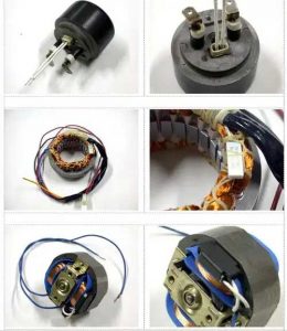
How to install thermal protector on motor coil
🔧 I. Core Installation Steps
Locate the Protector:
Determine the best placement for the thermal protector based on the motor’s design and the operating environment. It should be positioned to accurately monitor heat generation.
Wiring:
Carefully follow the manufacturer’s wiring diagrams to ensure correct and secure connections. Incorrect wiring can lead to malfunctions or false readings.
Protection Settings:
Adjust the temperature limit on the protector according to the motor’s design and the operating environment. This ensures that the protector shuts down the motor before it overheats.
Secure Installation:
Ensure the protector is securely mounted and that no wires are exposed or damaged.
Testing:
After installation, test the thermal protector to verify that it trips at the correct temperature setting.
Important Considerations:
Safety: Always disconnect power before working on any electrical equipment.
Overload Protection: Ensure the thermal protector is properly set to prevent overloads, which can damage the motor.
Consult Documentation: Refer to the manufacturer’s documentation for specific instructions and wiring diagrams.
By following these steps, you can ensure that your motor thermal protector is installed correctly and effectively protects the motor from overheating.
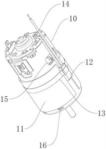
Installation method of built-in motor thermal protector
Power-off operation
Before installation, the main power must be cut off and the power must be checked to prevent electric shock accidents.
Determine the installation position
Conventional motor: Connect in series between the contactor output and the motor input (main circuit);
Star-delta starting motor: Preferentially install at the top of the main circuit to ensure full current monitoring.
Wiring specification
Power line→Connect to the protector input (marked “IN” or “L”);
Motor line→Connect to the output (marked “OUT” or “T1/T2”);
Lead wire processing: The bending point is ≥6mm from the root to avoid damage to the wire.
Fixed method
Anti-loosening washers are required when fixing with screws/rivets to prevent mechanical creep from causing poor contact.
Functional test
After power is restored, use a multimeter to detect the connectivity of the input and output terminals to simulate overheating to trigger a power-off response.
⚠️ II. Key pitfall avoidance guide
| Wrong operation | Correct method | Risk warning |
| Forced bending at the root of the lead | Gently bend 6mm away from the root | Protection failure caused by lead breakage |
| Thermal element on the side of the bimetal | The heating element is placed directly below the bimetal (accelerates heat conduction) | Action delay burns the motor |
| Not cooled after welding | Forced cooling ≥30 seconds after welding | Thermistor characteristic drift |
| Not selected according to the motor type | Delta motor must select differential phase loss protection type (such as JR20) | Protection blind area when phase is lost |
🔌 III. Precautions for special scenarios
Automobile motor
Disable pure mechanical protectors, and give priority to smart modules with integrated LIN bus (such as TI DRV5013) to avoid interference with the anti-pinch function.
Variable frequency motor
The protector needs to be >50cm away from the inverter, and the shielded wire is grounded to suppress electromagnetic interference.
Micro motor (such as drone)
Built-in PTC protectors (such as Murata POSISTOR®) need to be directly attached to the windings, and thermal grease should be applied to improve heat conduction efficiency.
Appendix: Setting current specification
Stable running motor: Setting current = motor rated current × (0.95~1.05)
Frequent start and stop motor: Setting current = rated current × 1.2 (need to cooperate with time relay)
✅ Acceptance standard
After manually triggering the protector, the contactor should trip within 0.5 seconds;
After continuous operation for 72 hours, the terminal temperature rise is ≤40K;
After the vibration test (ISO 16750), the protection function is normal.
Installation diagram example:
plaintext Copy Code
[Power] → [Circuit breaker] → [Contactor] → [Thermal protector] → [Motor]
↑
[Control circuit] ← [Protector auxiliary contact]
Note: The arrow points to the current direction
Following this process can avoid 90% of installation failures. It is recommended to check the oxidation of the contacts every month after the first installation.