 English
 Afrikaans
 العربية
 বাংলা
বাংলা bosanski jezik
 Български
 Català
 粤语
粤语 中文(简体)
 中文(漢字)
 Hrvatski
 Čeština
 Nederlands
 Eesti keel
 Suomi
Suomi Français
 Deutsch
 Ελληνικά
 हिन्दी; हिंदी
 Magyar
 Bahasa Indonesia
 Italiano
 日本語
日本語 한국어
한국어 Latviešu valoda
 Lietuvių kalba
 македонски јазик
 Bahasa Melayu
 Norsk
Norsk پارسی
پارسی Polski
 Português
 Română
 Русский
 Cрпски језик
 Slovenčina
 Slovenščina
 Español
 Svenska
 ภาษาไทย
 Türkçe
 Українська
 اردو
اردو Tiếng Việt


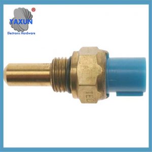
Cảm biến nhiệt độ nước là thành phần cốt lõi của hệ thống làm mát ô tô. Thành phần cốt lõi của nó là nhiệt điện trở NTC, được lắp đặt trên đầu xi lanh động cơ hoặc kênh nước. Thành phần này trông đơn giản, nhưng nó thực sự rất quan trọng đối với việc điều khiển động cơ. Nó sẽ ảnh hưởng trực tiếp đến việc điều chỉnh lượng phun và thời điểm đánh lửa của ECU..
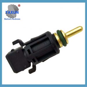 1433077 13621433077 MEK105210 NSC000100 cho hệ thống làm mát BMW cảm biến nhiệt độ nước |
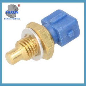
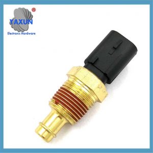 1/2Cảm biến nhiệt độ VDO nước NPT cho máy đo nhiệt độ nước dầu, 38oC~120oC |
 Cảm biến nhiệt độ nước động cơ 3/8 NPT 3W 103 Bộ phận tạo cảm biến nhiệt độ nước động cơ bằng đồng thau |
Điện trở của nhiệt điện trở bên trong cảm biến sẽ thay đổi theo nhiệt độ: nhiệt độ càng thấp, điện trở càng lớn, và nhiệt độ càng cao, điện trở càng nhỏ. ECU xác định nhiệt độ nước bằng cách đo sự thay đổi điện trở này. 8 Ghi chú bổ sung: Ở 30°C, điện trở thường nằm trong khoảng 1,4-1,9kΩ.
Vị trí lắp đặt cảm biến nhiệt độ nước rất khác nhau đối với các dòng máy khác nhau: Tràng hoa nằm bên phải khối trụ, Accord nằm ở mặt trước của động cơ, và Focus nằm ở phía sau khối trụ. Các mẫu hiện đại được lắp đặt nhiều hơn ở phía đầu xi lanh gần bộ điều chỉnh nhiệt.
Hiện tượng hư hỏng thường gặp của cảm biến nhiệt độ nước: khởi đầu khó khăn, tốc độ không tải không ổn định, đồng hồ đo nhiệt độ nước bất thường, vân vân. Động cơ cần tăng lượng phun thêm 30% ở nhiệt độ thấp, và nếu cảm biến bị lỗi, nó không thể được đền bù một cách chính xác.
Có năm cách để phát hiện cảm biến nhiệt độ nước: đo điện trở vạn năng, kiểm tra nước nóng, phân tích luồng dữ liệu, vân vân. Trong số đó, thử nghiệm gia nhiệt bằng đồng hồ vạn năng là phương pháp phát hiện tại chỗ được sử dụng phổ biến nhất.
Khi thay cảm biến nhiệt độ nước, chất làm mát phải được xả trước, nếu không sẽ gây ra hiện tượng hút khí vào hệ thống làm mát. Sau khi cài đặt, Việc niêm phong cũng cần được kiểm tra để tránh rò rỉ chất làm mát.
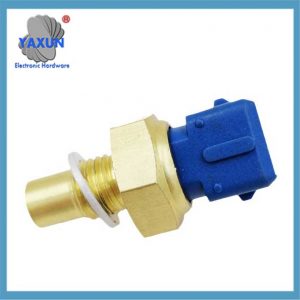
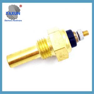 0015422317 A0105422317 0025425917 0005423717 3455427417 Công tắc cảm biến nhiệt độ nước làm mát |
 Công tắc nhiệt cảm biến xe ô tô Honda 37770-PY3-A01 37770PY3A01 |
 Áp dụng cho cảm biến nhiệt độ nước Daewoo Chevrolet 96279857 96325864 |
Sau đây là mô tả toàn diện về cảm biến nhiệt độ nước ô tô, được tổ chức kết hợp với nguyên tắc kỹ thuật, đặc điểm chức năng và điểm khắc phục sự cố:
TÔI. Cấu trúc cốt lõi và nguyên lý làm việc
1. Đặc tính nhiệt điện trở
Sử dụng hệ số nhiệt độ âm (NTC) vật liệu bán dẫn, giá trị điện trở giảm theo cấp số nhân khi nhiệt độ tăng (khoảng 2,5kΩ ở 20oC, và giảm xuống 0,3kΩ ở 80oC).
Sự thay đổi điện trở được chuyển thành tín hiệu điện (1.3-3.8Phạm vi tuyến tính V) thông qua mạch ba dây hoặc bốn dây và truyền đến bộ điều khiển động cơ (ECU).
2. Logic đầu ra tín hiệu
ECU tính toán nhiệt độ nước theo thời gian thực sau khi nhận được tín hiệu điện áp:
Điều kiện nhiệt độ thấp (-20oC): Tăng góc đánh lửa sớm thêm 8-12° và tăng lượng phun (+30% bồi thường khởi động nguội).
Điều kiện nhiệt độ cao (100oC): Trì hoãn góc đánh lửa sớm 4-6° để tránh nổ.
Ii. Vị trí và loại lắp đặt
| Phân loại vị trí | Tỷ lệ | Ví dụ mô hình điển hình |
| Đầu xi lanh/áo nước xi lanh | 65% | Toyota Corolla (bên phải của khối xi lanh) |
| Kênh nước gần bộ điều nhiệt | 22% | Honda Accord (phía trước động cơ) |
| Ống thoát tản nhiệt | 13% | Ford Focus (phía sau khối xi lanh) |
Ghi chú: Các mẫu hiện đại chủ yếu sử dụng cảm biến tích hợp bốn dây, được cố định ở giao diện bộ điều chỉnh nhiệt ở phía đầu xi lanh.
Iii. Giải thích chi tiết về chức năng và tác dụng
1. Điều khiển động cơ
Hiệu chỉnh nhiên liệu: tăng nồng độ tiêm ở nhiệt độ thấp và khôi phục lượng tiêm tham chiếu ở nhiệt độ cao.
Điều chỉnh tốc độ không tải: tăng tốc độ lên 1200-1500rpm ở nhiệt độ thấp (thông qua van điều khiển tốc độ không tải).
2. Quản lý hệ thống làm mát
Khi nhiệt độ nước ≥95oC, quạt làm mát được kích hoạt để khởi động (phối hợp với công tắc điều khiển nhiệt độ thường đóng).
Khi nhiệt độ tăng cao bất thường (>105oC), chế độ vận hành tốc độ cao của quạt được kích hoạt.
3. Dụng cụ và chẩn đoán
Đồng hồ đo nhiệt độ nước truyền động hiển thị nhiệt độ thời gian thực (lỗi <± 15oC là bình thường).
Mã lỗi đầu ra (chẳng hạn như P0115/P0118) để thiết bị chẩn đoán đọc được.
Iv. Biểu hiện và chẩn đoán lỗi
Các loại lỗi thường gặp
| Hiện tượng lỗi | Nguyên nhân gốc rễ | Tác động lên động cơ |
| Khởi đầu lạnh khó khăn | Hở mạch/ngắn mạch của nhiệt điện trở | ECU không thể cung cấp hỗn hợp giàu |
| Biến động tốc độ không tải/nhấp nháy | Tín hiệu trôi (giá trị điện trở bất thường) | Lỗi hiệu chỉnh phun nhiên liệu |
| Đồng hồ đo nhiệt độ nước hiển thị bất thường | Đường dây tiếp xúc kém hoặc hư hỏng cảm biến | Con trỏ bị kẹt hoặc chỉ báo nằm ngoài phạm vi |
| Quạt tiếp tục chạy | Tín hiệu nhiệt độ cao báo động sai (chẳng hạn như ngắn mạch đến cực dương) | ECU đánh giá sai là quá nóng |
Phương pháp chẩn đoán
1. Kiểm tra sức đề kháng
Tháo cảm biến và sử dụng đồng hồ vạn năng để đo điện trở giữa các cực:
30môi trường oC: giá trị điện trở bình thường 1,4-1,9kΩ.
80oC ngâm nước nóng: điện trở sẽ giảm xuống 0,3–0,4kΩ (nếu không thay đổi, sự thất bại).
2. Phân tích luồng dữ liệu
Dụng cụ chẩn đoán đọc luồng dữ liệu ECU:
Giá trị bình thường: 90–105oC (lái xe).
Lời nhắc lỗi: Hiển thị -40oC (hở mạch) hoặc 130oC không thay đổi (ngắn mạch).
V.. Phòng ngừa bảo trì
1. Thông số kỹ thuật hoạt động thay thế
Xả nước làm mát trước khi tháo cảm biến để tránh không khí lọt vào hệ thống làm mát.
Sử dụng chất bịt kín trong quá trình lắp đặt, và điều khiển mô-men xoắn đến 8–12N·m (phòng chống rò rỉ).
2. Lựa chọn và kết hợp mô hình
Phạm vi kháng cự: Cần phù hợp với đặc tính điện trở 275–6500Ω của xe nguyên bản.
Loại giao diện: Xác nhận các thông số kỹ thuật như ren M18×1.5 hoặc ren côn ZM14.
Cảnh báo: Lỗi cảm biến có thể khiến mức tiêu thụ nhiên liệu tăng hơn 15% hoặc hư hỏng vĩnh viễn cho động cơ, và cần được thay thế kịp thời.
Mã sao chép nàng tiên cá
đồ thị TD
MỘT[Lỗi cảm biến nhiệt độ nước] –> B{Các bước phát hiện}
B –> C[Đo điện trở vạn năng]
B –> D[Dụng cụ chẩn đoán đọc luồng dữ liệu]
C –>|Sức đề kháng bất thường| E[Thay thế cảm biến]
D –>|Tín hiệu trôi| E
C –>|Sức đề kháng bình thường| F[Kiểm tra nối đất đường dây]
D –>|Tín hiệu bình thường| G[Kiểm tra các hệ thống khác]