 English
 Afrikaans
 العربية
 বাংলা
বাংলা bosanski jezik
 Български
 Català
 粤语
粤语 中文(简体)
 中文(漢字)
 Hrvatski
 Čeština
 Nederlands
 Eesti keel
 Suomi
Suomi Français
 Deutsch
 Ελληνικά
 हिन्दी; हिंदी
 Magyar
 Bahasa Indonesia
 Italiano
 日本語
日本語 한국어
한국어 Latviešu valoda
 Lietuvių kalba
 македонски јазик
 Bahasa Melayu
 Norsk
Norsk پارسی
پارسی Polski
 Português
 Română
 Русский
 Cрпски језик
 Slovenčina
 Slovenščina
 Español
 Svenska
 ภาษาไทย
 Türkçe
 Українська
 اردو
اردو Tiếng Việt
1. PT100 och PT1000 temperaturresistans ändringstabell
Termiska motstånd av metall som nickel, koppar- och platinamotstånd har en positiv korrelation med förändringen i resistans med temperaturen. Platina har de mest stabila fysikaliska och kemiska egenskaperna och är den mest använda. Temperaturmätningsområdet för det vanliga platinamotståndet Pt100 är -200~850 ℃. Dessutom, temperaturmätningsområdena för Pt500, Pt1000, etc. successivt reduceras. Pt1000, temperaturmätningsområde -200~420 ℃. Enligt den internationella standarden IEC751, temperaturegenskaperna för platinamotståndet Pt1000 uppfyller följande krav:
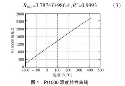
Pt1000 temperaturkarakteristikkurva
Enligt Pt1000 temperaturkarakteristikkurva, lutningen på motståndskarakteristikkurvan ändras lite inom det normala driftstemperaturområdet (som visas i figuren 1). Genom linjär passning, det ungefärliga förhållandet mellan motstånd och temperatur är:
1.1 PT100 temperaturmotståndsändringstabell
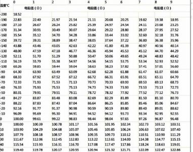
PT100 temperaturmotståndsändringstabell
1.2 PT1000 ändringstabell för temperaturmotstånd
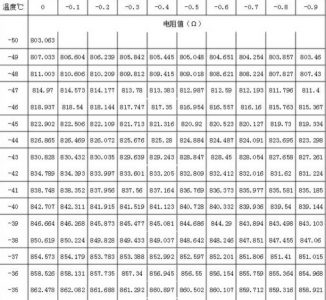
PT1000 Ändringstabell för temperaturmotstånd
2. Vanligt använda anskaffningskretslösningar
2.1 Motståndsspänningsdelningsutgång 0~3,3V/3V analog spänning
En-chip AD-port direkt förvärv
Temperaturmätningskretsens spänningsutgångsområde är 0~3,3V, PT1000 (PT1000 resistansvärde ändras kraftigt, temperaturmätningskänsligheten är högre än PT100; PT100 är mer lämplig för storskalig temperaturmätning).
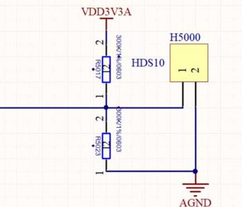
Motståndsspänningsavdelare utgångar 0 ~ 3.3V 3V analog spänning
Det enklaste sättet är att använda spänningsdelningsmetoden. Spänningen är spänningsreferenskällan 4V som genereras av TL431 -spänningsreferenschipet, eller Ref3140 kan användas för att generera 4.096V som referenskälla. Referenskällchips inkluderar också REF3120, 3125, 3130, 3133, och 3140. Chipet använder SOT-32-paket och 5V ingångsspänning. Utgångsspänningen kan väljas enligt den erforderliga referensspänningen. Naturligtvis, Enligt det normala spänningsingången för MCU -annonsen, det kan inte överstiga 3V/3.3V.
2.2 Motståndsspänningsdivision Output 0 ~ 5V Analog spänning MCU AD Port Direct Acquisition.
Naturligtvis, Vissa kretsar använder 5V MCU -strömförsörjning, och den maximala driftsströmmen för PT1000 är 0,5 mA, så lämpligt resistansvärde bör användas för att säkerställa att komponenterna fungerar normalt.
Till exempel, 3,3V i spänningsdelningsschemat ovan ersätts med 5V. Fördelen med detta är att 5V spänningsdelningen är känsligare än 3,3V, och förvärvet är mer exakt. Komma ihåg, den teoretiskt beräknade utspänningen får inte överstiga +5V. Annat, det kommer att orsaka skada på MCU.
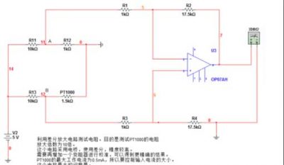
2.3 Den mest använda bromätningen
R11, R12, R13 och Pt1000 används för att bilda en mätbro, där R11=R13=10k, R12=1000R precisionsmotstånd. När motståndsvärdet för Pt1000 inte är lika med motståndsvärdet för R12, bron kommer att mata ut en spänningsskillnadssignal på mV-nivå. Denna spänningsskillnadssignal förstärks av instrumentförstärkarkretsen och matar ut den önskade spänningssignalen. Denna signal kan anslutas direkt till AD-omvandlingschippet eller AD-porten på mikrokontrollern.
R11, R12, R13 och Pt1000 används för att bilda en mätbrygga
Principen för resistansmätning av denna krets:
1) PT1000 är en termistor. När temperaturen ändras, motståndet förändras i princip linjärt.
2) På 0 grader, motståndet för PT1000 är 1kΩ, då är Ub och Ua lika, som är, Uba = Ub – Gör = 0.
3) Förutsatt att vid en viss temperatur, motståndet för PT1000 är 1,5 kΩ, då är inte Ub och Ua lika. Enligt spänningsdelningsprincipen, vi kan ta reda på att Uba = Ub – Do > 0.
4) OP07 är en operationsförstärkare, och dess spänningsförstärkning A beror på den externa kretsen, där A = R2/R1 = 17.5.
5) Utspänningen Uo för OP07 = Uba * A. Så om vi använder en voltmeter för att mäta utspänningen för OP07, vi kan sluta oss till värdet av Uab. Eftersom Ua är ett känt värde, vi kan vidare beräkna värdet av Ub. Sedan, med spänningsdelningsprincipen, vi kan beräkna det specifika resistansvärdet för PT1000. Denna process kan uppnås genom mjukvaruberäkning.
6) Om vi vet resistansvärdet för PT1000 vid vilken temperatur som helst, vi behöver bara slå upp tabellen utifrån resistansvärdet för att veta den aktuella temperaturen.
2.4 Konstant strömkälla
På grund av det termiska motståndets självuppvärmningseffekt, strömmen som flyter genom motståndet bör vara så liten som möjligt. I allmänhet, strömmen förväntas vara mindre än 10mA. Det har verifierats att självuppvärmningen av platinamotståndet PT100 av 1 mW kommer att orsaka en temperaturförändring på 0,02-0,75 ℃. Därför, Att minska strömmen i platinamotståndet PT100 kan också minska dess temperaturförändring. Dock, om strömmen är för liten, den är känslig för störningar, så värdet är generellt 0.5-2 mA, så den konstanta strömkällan väljs som en 1mA konstantströmkälla.
Chipet väljs som källchippet för konstant spänning TL431, och sedan omvandlas till en konstant strömkälla med ström negativ återkoppling. Kretsen visas i figuren
Bland dem, operationsförstärkaren CA3140 används för att förbättra strömkällans belastningskapacitet, och beräkningsformeln för utströmmen är:
Motståndet bör vara en 0.1% precisionsmotstånd. Den slutliga utströmmen är 0,996mA, som är, noggrannheten är 0.4%.
Den konstanta strömkällkretsen bör ha följande egenskaper
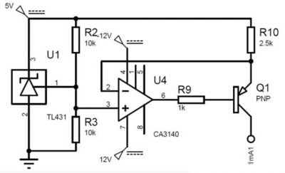
Välj konstant spänningskälla Chip TL431
Temperaturstabilitet: Eftersom vår temperaturmätningsmiljö är 0-100 ℃, Utgången från den nuvarande källan bör inte vara känslig för temperaturen. TL431 har en extremt låg temperaturkoefficient och låg temperaturdrift.
Bra belastningsreglering: Om den nuvarande krusningen är för stor, Det kommer att orsaka läsfel. Enligt teoretisk analys, Eftersom ingångsspänningen varierar mellan 100-138,5 mV, och temperaturmätningsområdet är 0-100 ℃, Temperaturmätningsnoggrannheten är ± 1 grad Celsius, så utgångsspänningen bör ändras med 38,5/100 = 0,385 mV för varje 1 ℃ Ökning av omgivningstemperatur. För att säkerställa att strömfluktuationen inte påverkar noggrannheten, överväga det mest extrema fallet, på 100 grader Celsius, motståndsvärdet för PT100 bör vara 138,5R. Då bör den nuvarande rippeln vara mindre än 0,385/138,5=0,000278mA, som är, strömändringen under laständringen bör vara mindre än 0,000278mA. I själva simuleringen, den nuvarande källan förblir i princip oförändrad.
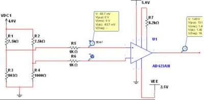
3. AD623 förvärvskretslösning
AD623 förvärv PT1000 kretslösning
Principen kan hänvisa till ovanstående bromätningsprincip.
Upptagning av låg temperatur:
Upptagning av hög temperatur
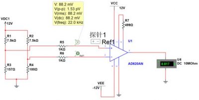
4. AD620 förvärvskretslösning
AD620 PT100 förvärvslösning
AD620 PT100 förvärvslösning hög temperatur (150°):
AD620 PT100 förvärvslösning låg temperatur (-40°):
AD620 PT100 insamlingslösning rumstemperatur (20°):
5. PT100 och PT1000 anti-interferensfiltreringsanalys
Temperaturförvärv i något komplex, hårda eller speciella miljöer kommer att bli föremål för stor inblandning, främst inklusive EMI och REI.
Till exempel, Vid tillämpningen av motortemperaturförvärv, Motorstyrning och höghastighetsrotation av motoren orsakar högfrekventa störningar.
Det finns också ett stort antal temperaturkontrollscenarier inom flyg- och rymdfordon, som mäter och kontrollerar kraftsystemet och miljökontrollsystemet. Kärnan i temperaturkontrollen är temperaturmätning. Eftersom termistornas motstånd kan förändras linjärt med temperaturen, Att använda platinamotstånd för att mäta temperatur är en effektiv temperaturmätningsmetod med hög precision. De viktigaste problemen är följande:
1. Motståndet på ledtråden introduceras lätt, vilket påverkar mätnoggrannheten hos sensorn;
2. I vissa miljöer med stark elektromagnetisk störning, störningen kan omvandlas till DC-utgång efter likriktning av instrumentförstärkaren
Offset fel, påverkar mätnoggrannheten.
5.1 Flygburen PT1000 anskaffningskrets
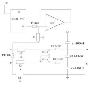
Flygburen PT1000 anskaffningskrets
Se designen av en luftburen PT1000-insamlingskrets för anti-elektromagnetiska störningar i en viss flygning.
Ett filter sätts i den yttersta änden av insamlingskretsen. PT1000 förvärvsförbehandlingskrets är lämplig för anti-elektromagnetisk störningsförbehandling av luftburen elektronisk utrustnings gränssnitt;
Den specifika kretsen är:
+15V inspänningen omvandlas till en +5V högprecisionsspänningskälla genom en spänningsregulator, och +5V högprecisionsspänningskällan är direkt ansluten till motståndet R1.
Den andra änden av motståndet R1 är uppdelat i två stigar, en ansluten till in-fas-ingången till OP-förstärkaren, och den andra ansluten till PT1000-motståndet ett slut genom T-typfiltret S1. Utgången från OP -förstärkaren är ansluten till inverterande ingången för att bilda en spänningsföljare, och inverteringsingången är ansluten till markporten för spänningsregulatorn för att säkerställa att spänningen vid in-fas-ingången alltid är noll. Efter att ha passerat S2 -filtret, I ena änden är ett av PT1000 -motståndet uppdelat i två stigar, En väg används som differentiell spänningsingång Terminal D genom motståndet R4, och den andra vägen är ansluten till AGND genom motstånd R2. Efter att ha passerat genom S3-filtret, den andra änden B av PT1000-motståndet är uppdelad i två banor, en väg används som differentialspänningsingångsklämman E genom motståndet R5, och den andra vägen är ansluten till AGND genom motståndet R3. D och E är anslutna via kondensator C3, D är ansluten till AGND via kondensator Cl, och E är ansluten till AGND via kondensatorn C2; det exakta resistansvärdet för PT1000 kan beräknas genom att mäta differentialspänningen mellan D och E.
+15V inspänningen omvandlas till en +5V högprecisionsspänningskälla genom en spänningsregulator. +5V är direkt ansluten till R1. Den andra änden av R1 är uppdelad i två banor, en är ansluten till in-fasingången på op-förstärkaren, och den andra är ansluten till PT1000-motståndet A genom T-typfiltret S1. Utgången från OP -förstärkaren är ansluten till inverterande ingången för att bilda en spänningsföljare, och inverteringsingången är ansluten till markporten för spänningsregulatorn för att säkerställa att spänningen vid inverteringsingången alltid är noll. Just nu, Strömmen som strömmar genom R1 är en konstant 0,5 mA. Spänningsregulatorn använder AD586TQ/883B, och OP AMP använder OP467A.
Efter att ha passerat S2 -filtret, I ena änden är ett av PT1000 -motståndet uppdelat i två stigar, en genom motståndet R4 som differentiell spänningsingång, och en genom motståndet R2 till AGND; Efter att ha passerat S3 -filtret, den andra änden B av PT1000-motståndet är uppdelad i två banor, en genom motståndet R5 som differentiell spänningsingång, och en genom motståndet R3 till AGND. D och E är anslutna via kondensator C3, D är ansluten till AGND via kondensator Cl, och E är ansluten till AGND via kondensatorn C2.
Motståndet för R4 och R5 är 4,02K ohm, Motståndet för R1 och R2 är 1 m ohm, Kapacitansen för C1 och C2 är 1000pf, och kapacitansen för C3 är 0,047uf. R4, R5, C1, C2, och C3 bildar tillsammans ett RFI -filternätverk, som slutför lågpassfiltreringen av insignalen, och de objekt som ska filtreras ut inkluderar differentiellt läge -interferens och vanliga läge -interferens som bärs i ingångsdifferentialsignalen. Beräkningen av avgränsningsfrekvensen –3DB för den vanliga läge -interferensen och differentiellt läge som bärs i insignalen visas i formeln:
Ersätta motståndsvärdet i beräkningen, Common Mode Cutoff -frekvensen är 40 kHz, och avgränsningsfrekvensen för differentialläge är 2,6 kHz.
Slutpunkt B är ansluten till AGND genom S4 -filtret. Bland dem, Filter markterminaler från S1 till S4 är alla anslutna till flygplanets skärmplan. Eftersom strömmen flyter genom PT1000 är en känd 0,05 mA, det exakta resistansvärdet för PT1000 kan beräknas genom att mäta differentialspänningen i båda ändarna av D och E.
S1 till S4 använder filter av T-typ, modell GTL2012X-103T801, med en gränsfrekvens på 1M±20 %. Denna krets introducerar lågpassfilter till de externa gränssnittslinjerna och utför RFI-filtrering på differentialspänningen. Som en förbehandlingskrets för PT1000, det eliminerar effektivt elektromagnetiska störningar och RFI-strålningsstörningar, vilket avsevärt förbättrar tillförlitligheten hos de insamlade värdena. Dessutom, spänningen mäts direkt från båda ändarna av PT1000-motståndet, eliminera felet som orsakas av ledningsresistansen och förbättra noggrannheten hos resistansvärdet.
5.2 T-typ filter
T-filtret består av två induktorer och kondensatorer. Båda ändarna av den har hög impedans, och dess insättningsförlustprestanda liknar den för filtret av π-typ, men det är inte benäget att “ringande” och kan användas i omkopplingskretsar.
