Kategorie produktów
- bezpiecznik termiczny 32
- bezpieczniki do montażu powierzchniowego 12
- termistor 36
- Uchwyt bezpiecznika do montażu na płytce drukowanej 27
- Wiązka przewodów 6
- Uchwyty bezpieczników ostrza 17
- termostat 50
- Bezpiecznik elektryczny 24
- Motorowy czujnik temperatury 7
- Wyłącznik termiczny 22
- Uchwyt skrzynki bezpieczników 36
- Czujnik temperatury 75
- Wyłącznik termiczny 68
- Bezpiecznik samochodowy 20
- Przykręcić bezpieczniki 8
Tagi produktów
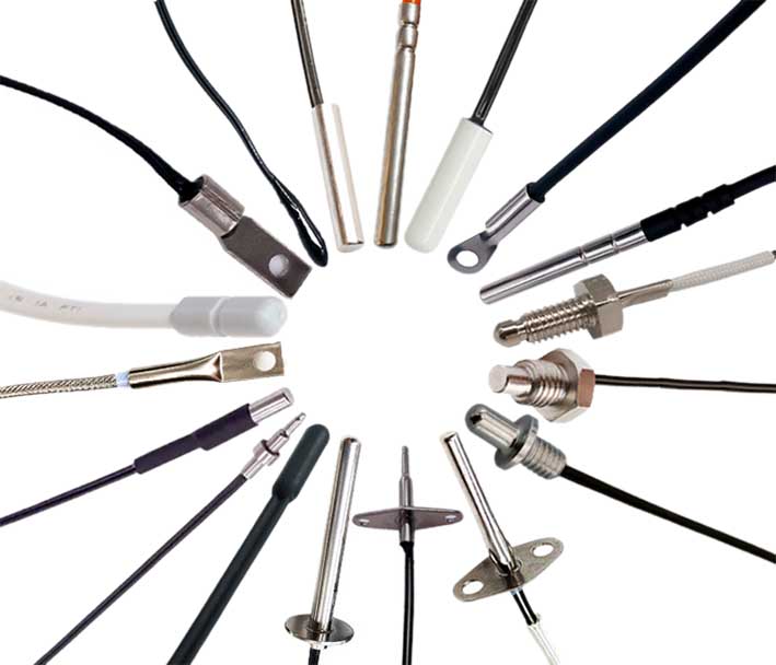
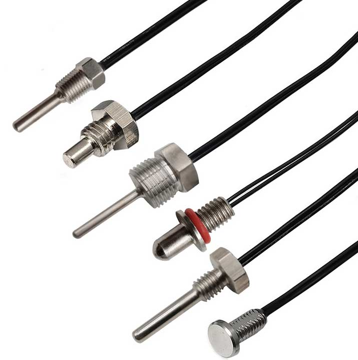
Sonda czujnika i kabel DS18b20
Funkcje czujnika temperatury DS18B20: wodoodporny, antykorozyjne.
Szczegóły opakowania: można dostosować według potrzeb. MAXIM importowany z oryginalnym opakowaniem; Pakiet TO-92; duże ilości w magazynie. I zapewnij cyfrowy czujnik temperatury DS18B20 w wodoodpornej obudowie ze stali nierdzewnej.
The ds18b20 temperature sensor probe has high accuracy. The temperature measurement accuracy can reach 0.01℃, and the temperature measurement accuracy in the wide temperature range is 0.1℃. Good stability and high precision in mass production.
The DS18B20 digital sensor probe and cable are easy to connect and can be used in a variety of situations after being packaged. Such as stainless steel straight pipe type, typ gwintowany, typ adsorpcji magnetycznej, różne modele, w tym LTM8877, LTM8874 i tak dalej.
DS18B20 to powszechnie stosowany cyfrowy czujnik temperatury. It outputs a digital signal and has the characteristics of small size, niskie obciążenie sprzętowe, strong anti-interference ability and high accuracy. Its appearance mainly changes depending on the application. The encapsulated DS18B20 can be used for cable temperature measurement, blast furnace water circulation temperature measurement, boiler temperature measurement, machine room temperature measurement, agricultural greenhouse temperature measurement, clean room temperature measurement, ammunition depot temperature measurement and other non-limit temperature occasions. Wear-resistant and impact-resistant, mały rozmiar, łatwy w użyciu, with various packaging forms, it is suitable for digital temperature measurement and control of various small space equipment.
Main features of DS18B20 sensor probe
1. Main features of DS18B20
1.1. The adaptable voltage range is wider, voltage range: 3.0~5.5V, and can be powered by the data line in parasitic power mode
1.2. Unique single-wire interface method. When DS18B20 is connected to the microprocessor, it only needs one port line to achieve two-way communication between the microprocessor and DS18B20.
1.3. DS18B20 supports multi-point networking function. Multiple DS18B20 can be connected in parallel on the only three lines to achieve multi-point temperature measurement.
1.4. DS18B20 does not require any external components during use. All sensing components and conversion circuits are integrated into an integrated circuit shaped like a triode.
1.5. Temperature range -55℃~+125℃, accuracy is ±0.5℃ at -10~+85℃
1.6. The programmable resolution is 9~12 bits, and the corresponding resolvable temperatures are 0.5℃, 0.25℃, 0.125℃ and 0.0625℃ respectively, which can achieve high-precision temperature measurement.
1.7. At 9-bit resolution, the temperature can be converted into numbers in up to 93.75ms. At 12-bit resolution, the temperature value can be converted into numbers in up to 750ms, which is faster.
1.8. The measurement results directly output digital temperature signals and are serially transmitted to the CPU via the "autobus jednoliniowy". Naraz, the CRC check code can be transmitted, which has strong anti-interference and error correction capabilities.
1.9. Negative voltage characteristics: When the polarity of the power supply is reversed, the chip will not be burned due to heat, but it will not work properly.
2. Appearance and internal structure of DS18B20 sensor
The internal structure of the DS18B20 sensor mainly consists of four parts: 64-bitowa pamięć ROM z fotolitografią, czujnik temperatury, nieulotny alarm temperatury wyzwala TH i TL, and configuration register.
The appearance and pin arrangement of DS18B20 are as follows:
DS18B20 pin definition:
(1) DQ to terminal wejścia/wyjścia sygnału cyfrowego;
(2) GND to masa zasilania;
(3) VDD is the input terminal of the external power supply (uziemione w pasożytniczym trybie okablowania zasilania).
3. Working principle of DS18B20
The reading and writing timing and temperature measurement principle of DS18B20 are the same as those of DS1820, except that the number of digits of the temperature value obtained is different due to different resolutions, a czas opóźnienia podczas konwersji temperatury został zmniejszony z 2 s do 750 ms. The oscillation rate of high temperature coefficient crystal oscillator changes significantly with temperature changes, a wygenerowany sygnał wykorzystywany jest jako wejście impulsowe licznika 2. Counter 1 and the temperature register are preset at a base value corresponding to -55°C. Counter 1 counts down the pulse signal generated by the low temperature coefficient crystal oscillator. When the preset value of counter 1 decreases to 0, the value of the temperature register will be increased by 1, the preset value of counter 1 will be reloaded, and counter 1 will restart counting the pulse signals generated by the low temperature coefficient crystal oscillator. This cycle continues until counter 2 counts to 0, then stops accumulating the temperature register value. W tej chwili, the value in the temperature register is the measured temperature. The slope accumulator in Figure 3 is used to compensate and correct the nonlinearity in the temperature measurement process, and its output is used to correct the preset value of counter 1.

ds18b20 sensor with accuracy up to 0.01℃

Dostosowana sonda czujnika ds18b20 i kabel
DS18B20 has 4 main data components:
(1) The 64-bit serial number in the photoetched ROM is photoetched before leaving the factory. Można go uważać za kod seryjny adresu DS18B20. Układ 64-bitowej pamięci ROM z fotolitografią jest taki: pierwszy 8 bity (28H) to numer typu produktu, and the next 48 bity to numer seryjny samego DS18B20. The last 8 bits are the cyclic redundancy check code of the previous 56 bity (CRC=X8+X5+X4+1). The function of photolithography ROM is to make each DS18B20 different, dzięki czemu do jednej magistrali można podłączyć wiele DS18B20.
(2) Czujnik temperatury w DS18B20 może zakończyć pomiar temperatury. Weźmy jako przykład konwersję 12-bitową: it is provided in the form of 16-bit sign-extended two's complement reading, wyrażona w postaci 0,0625°C/LSB, gdzie S jest bitem znaku.
Są to 12-bitowe dane uzyskane po 12-bitowej konwersji, który jest przechowywany w dwóch 8-bitowych pamięciach RAM 18B20. Pierwszy 5 bits in binary are the sign bits. If the measured temperature is greater than 0, te 5 bity są 0. Wystarczy pomnożyć zmierzoną wartość przez 0.0625 aby uzyskać rzeczywistą temperaturę. Jeśli temperatura jest niższa niż 0, te 5 bity są 1, i zmierzoną wartość należy odwrócić, plus 1, a następnie pomnożone przez 0.0625 aby uzyskać rzeczywistą temperaturę. Na przykład, wyjście cyfrowe +125 ℃ wynosi 07D0H, wyjście cyfrowe +25,0625 ℃ to 0191H, wyjście cyfrowe -25,0625℃ to FE6FH, a wyjście cyfrowe -55 ℃ to FC90H.
(3) DS18B20 temperature sensor memory DS18B20. The internal memory of the temperature sensor includes a high-speed scratchpad RAM and a non-volatile electrically erasable EEPRAM, which stores the high-temperature and low-temperature flip-flops TH, Rejestry TL i strukturalne.
(4) Configuration register The meaning of each bit of this byte is as follows:
Tabela 3: Configuration register structure
Zawsze jest pięć niższych bitów "1", and TM is the test mode bit, który służy do ustawienia, czy DS18B20 znajduje się w trybie pracy, czy w trybie testowym. Ten bit jest ustawiony na 0 gdy DS18B20 opuszcza fabrykę, i użytkownicy nie powinni tego zmieniać. R1 i R0 służą do ustawiania rozdzielczości, jak pokazano w poniższej tabeli: (DS18B20 jest ustawione na 12 bitów po wysłaniu z fabryki)
Tabela 4: Temperature resolution setting table
4. High-speed temporary storage memory The high-speed temporary storage memory consists of 9 bajty, and its allocation is shown in Table 5. When the temperature conversion command is issued, the converted temperature value is stored in the 0th and 1st bytes of the cache memory in two-byte complement form. The microcontroller can read this data through the single-wire interface. When reading, the low bit is in front and the high bit is in the back. The data format is shown in Table 1. Corresponding temperature calculation: When the sign bit S=0, directly convert the binary bit to decimal; when S=1, first convert the complement to the original code, and then calculate the decimal value. Tabela 2 shows some of the corresponding temperature values. Bajt dziewiąty jest bajtem kontroli redundancji.
Tabela 5: DS18B20 temporary register distribution
Zgodnie z protokołem komunikacyjnym DS18B20, the host (single chip microcomputer) must go through three steps to control DS18B20 to complete temperature conversion: DS18B20 należy zresetować przed każdym odczytem i zapisem. After the reset is successful, a ROM command is sent, and finally a RAM command is sent, so that the predetermined operation can be performed on the DS18B20. Reset wymaga, aby główny procesor obniżył linię danych 500 mikrosekund, a następnie zwolnij go. When DS18B20 receives the signal, it waits for about 16 Do 60 Microsekunds, a następnie wysyła niski impuls 60 Do 240 Microsekunds. Główny procesor otrzymuje ten sygnał, aby wskazać pomyślny reset.
Tabela 6: ROM instruction list
Skontaktuj się z nami
Czekam na Twój e-mail, odpowiemy Ci w ciągu 12 godziny z cennymi informacjami, których potrzebujesz.
 English
 Afrikaans
 العربية
 বাংলা
বাংলা bosanski jezik
 Български
 Català
 粤语
粤语 中文(简体)
 中文(漢字)
 Hrvatski
 Čeština
 Nederlands
 Eesti keel
 Suomi
Suomi Français
 Deutsch
 Ελληνικά
 हिन्दी; हिंदी
 Magyar
 Bahasa Indonesia
 Italiano
 日本語
日本語 한국어
한국어 Latviešu valoda
 Lietuvių kalba
 македонски јазик
 Bahasa Melayu
 Norsk
Norsk پارسی
پارسی Polski
 Português
 Română
 Русский
 Cрпски језик
 Slovenčina
 Slovenščina
 Español
 Svenska
 ภาษาไทย
 Türkçe
 Українська
 اردو
اردو Tiếng Việt

