Produktų kategorijos
- Šilumos saugiklis 32
- Paviršiaus laikikliai 12
- Termistorius 36
- PCB kalno saugiklių laikiklis 27
- Laidų diržai 6
- Ašmenų saugiklių laikikliai 17
- Termostatas 50
- Elektrinis saugiklis 24
- Automobilių temperatūros jutiklis 7
- Šilumos grandinės pertraukiklis 22
- „Fuse Box Holder“ 36
- Temperatūros jutiklis 75
- Šiluminis jungiklis 68
- Automobilių saugiklis 20
- Varžtas žemyn 8
Produktų žymos
Ds18b20 jutiklio zondas ir kabelis
DS18B20 temperatūros jutiklio savybės: atsparus vandeniui, antikorozinis.
Pakuotės detalės: galima pritaikyti pagal poreikį. MAXIM importuotas su originalia pakuote; TO-92 paketas; dideli kiekiai sandėlyje. Ir pateikite DS18B20 skaitmeninį temperatūros jutiklį nerūdijančio plieno vamzdžių vandeniui atsparioje pakuotėje.
The ds18b20 temperature sensor probe has high accuracy. The temperature measurement accuracy can reach 0.01℃, and the temperature measurement accuracy in the wide temperature range is 0.1℃. Good stability and high precision in mass production.
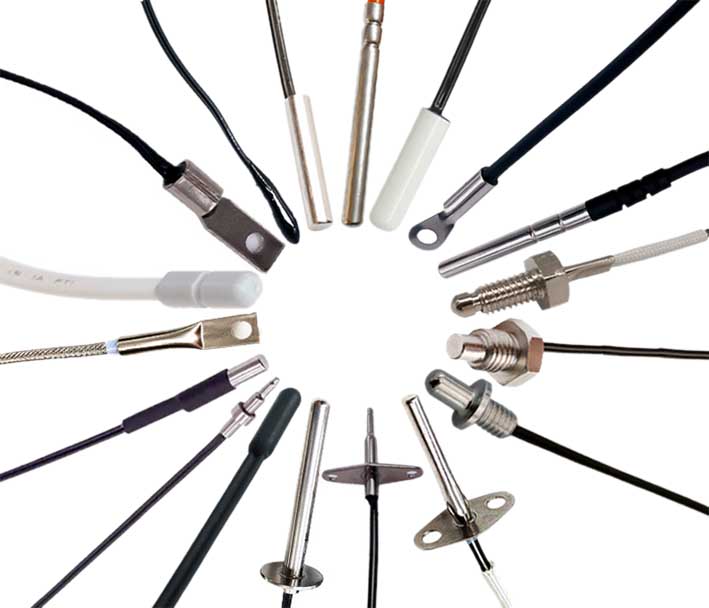
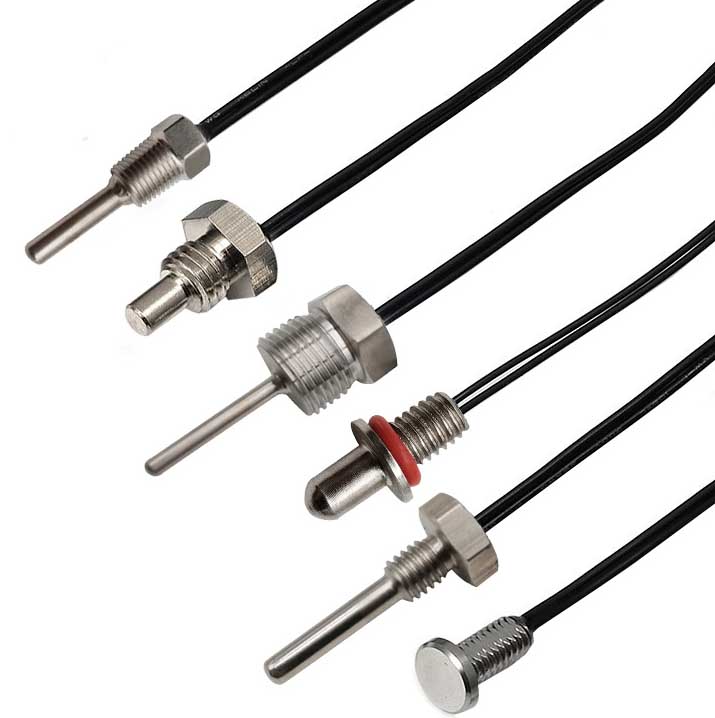
The DS18B20 digital sensor probe and cable are easy to connect and can be used in a variety of situations after being packaged. Such as stainless steel straight pipe type, srieginis tipas, Magneto adsorbcijos tipas, Įvairūs modeliai, įskaitant LTM8877, LTM8874 ir pan.
DS18B20 yra dažniausiai naudojamas skaitmeninis temperatūros jutiklis. It outputs a digital signal and has the characteristics of small size, žemos techninės įrangos išlaidos, strong anti-interference ability and high accuracy. Jo išvaizda daugiausia keičiasi priklausomai nuo taikymo. Įkapsuliuotą DS18B20 galima naudoti kabelio temperatūrai matuoti, aukštakrosnės vandens cirkuliacijos temperatūros matavimas, katilo temperatūros matavimas, machine room temperature measurement, žemės ūkio šiltnamio temperatūros matavimas, švarios patalpos temperatūros matavimas, šaudmenų sandėlio temperatūros matavimas ir kitos neribotos temperatūros progos. Atsparus dilimui ir smūgiams, mažo dydžio, lengva naudoti, su įvairiomis pakuotėmis, tinka skaitmeniniam temperatūros matavimui ir įvairios mažos erdvės įrangos valdymui.
Main features of DS18B20 sensor probe
1. Pagrindinės DS18B20 savybės
1.1. The adaptable voltage range is wider, įtampos diapazonas: 3.0~5.5V, and can be powered by the data line in parasitic power mode
1.2. Unikalus vieno laido sąsajos metodas. Kai DS18B20 yra prijungtas prie mikroprocesoriaus, jam tereikia vienos prievado linijos, kad būtų užtikrintas dvipusis ryšys tarp mikroprocesoriaus ir DS18B20.
1.3. DS18B20 palaiko kelių taškų tinklo funkciją. Multiple DS18B20 can be connected in parallel on the only three lines to achieve multi-point temperature measurement.
1.4. DS18B20 does not require any external components during use. All sensing components and conversion circuits are integrated into an integrated circuit shaped like a triode.
1.5. Temperature range -55℃~+125℃, accuracy is ±0.5℃ at -10~+85℃
1.6. The programmable resolution is 9~12 bits, and the corresponding resolvable temperatures are 0.5℃, 0.25℃, 0.125℃ and 0.0625℃ respectively, which can achieve high-precision temperature measurement.
1.7. At 9-bit resolution, the temperature can be converted into numbers in up to 93.75ms. At 12-bit resolution, the temperature value can be converted into numbers in up to 750ms, which is faster.
1.8. The measurement results directly output digital temperature signals and are serially transmitted to the CPU via the "one-line bus". Tuo pačiu metu, the CRC check code can be transmitted, which has strong anti-interference and error correction capabilities.
1.9. Negative voltage characteristics: When the polarity of the power supply is reversed, the chip will not be burned due to heat, but it will not work properly.
2. Appearance and internal structure of DS18B20 sensor
The internal structure of the DS18B20 sensor mainly consists of four parts: 64-bitų fotolitografijos ROM, Temperatūros jutiklis, nepastovios temperatūros aliarmas suveikia TH ir TL, and configuration register.
The appearance and pin arrangement of DS18B20 are as follows:
DS18B20 kaiščio apibrėžimas:
(1) DQ yra skaitmeninio signalo įvesties/išvesties terminalas;
(2) GND yra maitinimo įžeminimas;
(3) VDD is the input terminal of the external power supply (grounded in the parasitic power wiring mode).
3. Working principle of DS18B20
The reading and writing timing and temperature measurement principle of DS18B20 are the same as those of DS1820, except that the number of digits of the temperature value obtained is different due to different resolutions, and the delay time during temperature conversion is reduced from 2s to 750ms. The oscillation rate of high temperature coefficient crystal oscillator changes significantly with temperature changes, o sugeneruotas signalas naudojamas kaip skaitiklio impulsų įvestis 2. Skaitliukas 1 ir temperatūros registras yra iš anksto nustatytas bazine verte, atitinkančia -55°C. Skaitliukas 1 skaičiuoja žemos temperatūros koeficiento kristalinio generatoriaus generuojamą impulsinį signalą. Kai iš anksto nustatyta skaitiklio vertė 1 sumažėja iki 0, temperatūros registro reikšmė bus padidinta 1, iš anksto nustatyta skaitiklio vertė 1 bus perkrautas, ir skaitiklis 1 iš naujo pradės skaičiuoti impulsų signalus, kuriuos generuoja žemos temperatūros koeficiento kristalinis generatorius. Šis ciklas tęsiasi iki skaitiklio 2 skaičiuoja 0, tada nustoja kaupti temperatūros registro reikšmę. Šiuo metu, reikšmė temperatūros registre yra išmatuota temperatūra. The slope accumulator in Figure 3 is used to compensate and correct the nonlinearity in the temperature measurement process, ir jo išvestis naudojama iš anksto nustatytai skaitiklio vertei pataisyti 1.

ds18b20 sensor with accuracy up to 0.01℃

Individualus ds18b20 jutiklio zondas ir kabelis
DS18B20 has 4 main data components:
(1) The 64-bit serial number in the photoetched ROM is photoetched before leaving the factory. It can be regarded as the address serial code of the DS18B20. The arrangement of the 64-bit photolithography ROM is: pirmasis 8 bitai (28H) are the product type number, and the next 48 bits are the serial number of the DS18B20 itself. The last 8 bits are the cyclic redundancy check code of the previous 56 bitai (CRC=X8+X5+X4+1). The function of photolithography ROM is to make each DS18B20 different, kad prie vienos magistralės būtų galima prijungti kelis DS18B20.
(2) The temperature sensor in DS18B20 can complete the measurement of temperature. Take 12-bit conversion as an example: it is provided in the form of 16-bit sign-extended two's complement reading, expressed in the form of 0.0625°C/LSB, kur S yra ženklo bitas.
This is the 12-bit data obtained after 12-bit conversion, which is stored in two 8-bit RAMs of 18B20. Pirmoji 5 bits in binary are the sign bits. Jei išmatuota temperatūra yra didesnė nei 0, šie 5 bitai yra 0. Tiesiog padauginkite išmatuotą vertę iš 0.0625 Norėdami gauti tikrąją temperatūrą. Jei temperatūra žemesnė nei 0, šie 5 bitai yra 1, and the measured value needs to be inverted, plus 1, ir tada padauginta iš 0.0625 Norėdami gauti tikrąją temperatūrą. Pavyzdžiui, skaitmeninė +125 ℃ išvestis yra 07D0H, skaitmeninė +25,0625 ℃ išvestis yra 0191H, the digital output of -25.0625℃ is FE6FH, ir skaitmeninė išvestis -55 ℃ yra FC90H.
(3) DS18B20 temperature sensor memory DS18B20. The internal memory of the temperature sensor includes a high-speed scratchpad RAM and a non-volatile electrically erasable EEPRAM, which stores the high-temperature and low-temperature flip-flops TH, TL and structural registers.
(4) Configuration register The meaning of each bit of this byte is as follows:
Lentelė 3: Configuration register structure
The lower five bits are always "1", and TM is the test mode bit, which is used to set whether the DS18B20 is in working mode or test mode. This bit is set to 0 when DS18B20 leaves the factory, and users should not change it. R1 and R0 are used to set the resolution, as shown in the following table: (DS18B20 is set to 12 bitai, kai jie buvo išsiųsti iš gamyklos)
Lentelė 4: Temperature resolution setting table
4. High-speed temporary storage memory The high-speed temporary storage memory consists of 9 baitų, and its allocation is shown in Table 5. When the temperature conversion command is issued, the converted temperature value is stored in the 0th and 1st bytes of the cache memory in two-byte complement form. The microcontroller can read this data through the single-wire interface. When reading, the low bit is in front and the high bit is in the back. The data format is shown in Table 1. Corresponding temperature calculation: When the sign bit S=0, directly convert the binary bit to decimal; when S=1, first convert the complement to the original code, and then calculate the decimal value. Lentelė 2 shows some of the corresponding temperature values. The ninth byte is the redundancy check byte.
Lentelė 5: DS18B20 temporary register distribution
According to the communication protocol of DS18B20, the host (single chip microcomputer) must go through three steps to control DS18B20 to complete temperature conversion: DS18B20 must be reset before each read and write. After the reset is successful, a ROM command is sent, and finally a RAM command is sent, so that the predetermined operation can be performed on the DS18B20. Reset requires the main CPU to pull the data line down for 500 microseconds and then release it. When DS18B20 receives the signal, it waits for about 16 į 60 mikrosekundės, and then sends out a low pulse of 60 į 240 mikrosekundės. The main CPU receives this signal to indicate successful reset.
Lentelė 6: ROM instruction list
Susisiekite su mumis
Laukiu jūsų el. Pašto, Mes jums atsakysime 12 Valandos su vertinga informacija, kurios jums reikėjo.
 English
 Afrikaans
 العربية
 বাংলা
বাংলা bosanski jezik
 Български
 Català
 粤语
粤语 中文(简体)
 中文(漢字)
 Hrvatski
 Čeština
 Nederlands
 Eesti keel
 Suomi
Suomi Français
 Deutsch
 Ελληνικά
 हिन्दी; हिंदी
 Magyar
 Bahasa Indonesia
 Italiano
 日本語
日本語 한국어
한국어 Latviešu valoda
 Lietuvių kalba
 македонски јазик
 Bahasa Melayu
 Norsk
Norsk پارسی
پارسی Polski
 Português
 Română
 Русский
 Cрпски језик
 Slovenčina
 Slovenščina
 Español
 Svenska
 ภาษาไทย
 Türkçe
 Українська
 اردو
اردو Tiếng Việt

