 English
 Afrikaans
 العربية
 বাংলা
বাংলা bosanski jezik
 Български
 Català
 粤语
粤语 中文(简体)
 中文(漢字)
 Hrvatski
 Čeština
 Nederlands
 Eesti keel
 Suomi
Suomi Français
 Deutsch
 Ελληνικά
 हिन्दी; हिंदी
 Magyar
 Bahasa Indonesia
 Italiano
 日本語
日本語 한국어
한국어 Latviešu valoda
 Lietuvių kalba
 македонски јазик
 Bahasa Melayu
 Norsk
Norsk پارسی
پارسی Polski
 Português
 Română
 Русский
 Cрпски језик
 Slovenčina
 Slovenščina
 Español
 Svenska
 ภาษาไทย
 Türkçe
 Українська
 اردو
اردو Tiếng Việt


自動車吸気温度センサーの関連知識. この問題は自動車整備や電子制御の分野でよく見られます。.
自動車吸気温度センサーのいくつかのポイント: 初め, すべての材料は、これが負の温度係数であることを強調しています (NTC) サーミスタセンサー, それはその動作原理を理解するための基礎です. 第二に, 設置位置には 2 つの主流ソリューションがあります (スロットルの前/後), しかし機能は同じです. 障害症状セクション, 複数の情報筋は、始動困難やアイドリング速度の不安定などの典型的な症状について繰り返し言及している。, 冗長性を避けるために統合する必要があるもの.
吸気温度センサーと排気温度センサーの違いの比較に特に注意してください。. この知識ポイントは、吸気温度センサーの特殊性を理解するのに非常に役立ちます。, そしてそれについて簡単に言及することを検討してください. 技術的なパラメータに関しては, 車の高温および低温条件下での信号電圧の差は非常に貴重であり、センサーの動的な動作特性を反映する可能性があると述べられています。.
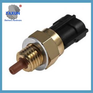
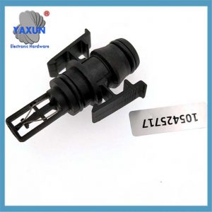 メルセデスベンツ吸気温度センサー 105425717 |
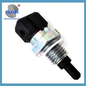
 吸気温度センサー 8942412010 トヨタ用 KL47-18-845 89424-12010 |
 ボッシュセンサー吸気温度 Audi BMW OPEL SEAT VW HONDA OE 046906379 |
構造化されたプレゼンテーションを使用する準備をする: 最初に定義と基本原則の概要を説明します, そしてそれを3つの部分に分けて展開します: ワークフロー, 関数, そして過失.
吸気温度センサー (IAT) エンジン管理システムの重要なコンポーネントです. エンジンに入る空気の温度を監視し、データを電気信号に変換して電子制御ユニットに送信するために使用されます。 (ECU) 噴射量や点火時期などのパラメータを正確に補正するため. 以下はそのコアポイントです:
私. 動作原理と構造
「コアコンポーネント」
負の温度係数を採用 (NTC) サーミスター: 温度が上がると抵抗値が下がります, 温度が下がると抵抗値が増加します.
信号変換
センサーとECUは閉回路を形成します. ECUは5Vの基準電圧を提供します (THA線) もう1つはアース線です (E2). 温度変化により抵抗が変化する, これにより回路電圧が変化し、温度に応じた電気信号が生成されます。.
IAT センサーは、エンジンのインテークマニホールドに入る空気の温度を測定します。.
この情報は、ECU が最適な燃焼のための適切な混合気と点火タイミングを計算するために重要です。.
ECUはセンサーに電圧を送信し、センサー両端の電圧降下を読み取ります。, これは吸気温度に相当します.
信号特性
冷えた車内状態: 信号電圧は水温センサーと同様;
車内の高温状態: 信号電圧は水温センサーの約2~3倍.
 温度センサー 8Z0820535A アウディ A3 A4 S4 S5 クアット Q3 Q5 Q7 VW ゴルフに適合 |
 MD326170 13650-56B00 三菱ランサー吸気水温センサーに適用 |
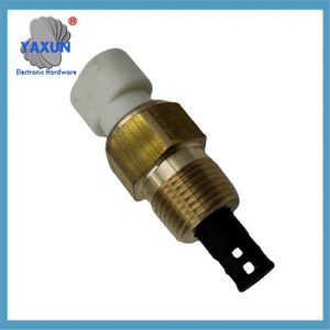 吸気温度センサー IAT, マット, GM用ACTキット 25036751 25037225 25037334 |
Ⅱ. 設置場所と機能⌌
設置場所
インテークパイプまたはエアフロメーター内に設置, スロットルの前のどちらか (インテークパイプ) またはスロットル後 (インテークマニホールド).
「コア機能」
空燃比補正: 低温の空気は密度が高い, そのため、ECUは燃料噴射量を増加させます; 高温の空気は密度が低い, 最適な燃焼効率を確保するために燃料噴射量が削減されます。.
ノッキング予防: 吸入空気が高温になるとノッキングが発生しやすくなります, ECUはそれに応じて点火進角を調整します.
ターボプロテクション: 過給後の空気温度を監視し、過熱による損傷を防ぎます。.
III. 障害の症状と診断
代表的な故障現象
始動が難しい, アイドリング回転数が不安定, そして加速が弱い;
過剰な排気ガス (黒煙);
エンジン故障ランプが点灯している.
障害の原因と影響
| 障害の種類 | データ フローのパフォーマンス | 混合物への影響 | 根本的な原因 |
|---|---|---|---|
| 接地不良 | 異常な低温 | 豊かすぎる | 噴射パルス幅増加 |
| センサーの短絡 | 異常高温 | 痩せすぎ | 噴射パルス幅の縮小 |
| センサー断線 | 信号損失 | 痩せすぎ | ECUはプリセット値を使用します, 始めるのが難しい |
検出方法
抵抗検出: センサーを取り外します, 加熱後の抵抗値を測定する (ヘアドライヤーの使用など), そしてそれを基準値と比較してください;
電圧検出: イグニッションスイッチがONのとき, THAとE2の間の電圧を測定します (常温で約0.5~3.4V).
iv. 他の温度センサーとの違い 排気温度センサーとの比較
| パラメータ | 吸気温度センサー | 排気温度センサー |
|---|---|---|
| 動作範囲 | -40℃〜150℃ | 200℃~1000℃ (さらに高い) |
| 設置場所 | インテークパイプ/エアフローメーター | エキゾーストマニホールド/ニア三元触媒コンバーター |
| コア機能 | 空燃比の最適化 | 触媒を保護する, DPF再生制御 |
| 材料要件 | 従来の包装 (プラスチック/エポキシ樹脂) | 高温耐性のある金属ハウジング (ステンレス鋼など) |
V. 技術の進化と重要性
NTCサーミスタの代表的な用途として, このセンサーは、シンプルな物理特性によって高精度の温度フィードバックを実現します。, エンジンパワーに直接影響する, 燃費と排出ガスレベル. 小さいデザインですが、, 閉ループ制御を実現するための現代の電子制御システムの不可欠な部分です。.
IAT センサー機能をカスタマイズする理由?
パフォーマンスチューニング:
IAT 信号を変更すると、エンジンのパフォーマンスを微調整することができます. 例えば, わずかに低い吸気温度をシミュレートすると、燃料混合がより濃くなり、出力が増加する場合があります。, 特にターボエンジンの場合.
改造に対する補償:
吸気システムを改造した場合 (例えば, インテークマニホールドを交換しました, 冷気取り入れ口を追加しました), IAT センサーが純正とは異なる温度を読み取る可能性があります. センサーの出力をカスタマイズすると、これらの変化を補正するのに役立ちます.
テストと実験:
IAT センサーを変更すると、さまざまなエンジン パラメーターを試して、パフォーマンスへの影響を観察することができます。.
カスタマイズ方法:
抵抗を加える:
シリーズで: IAT センサーと直列に抵抗を追加すると、全体の抵抗が増加します。, ECU がより低い温度を解釈するようにする.
並行して: 抵抗を並列に追加すると、全体の抵抗が減少します。, ECUがより高い温度を解釈する原因となる.
ポテンショメータ (可変抵抗器):
ポテンショメータを使用すると、抵抗と抵抗を調整できます。, したがって, 動的に知覚される吸気温度.
これは、特定のセットアップに最適な設定を見つけるのに役立ちます.
センサーの位置:
IAT センサーの位置も、熱浸みにより読み取り値に影響を与える可能性があります。. 調整するときはこれを考慮してください.
ECUキャリブレーション:
一部のアフターマーケット ECU では、IAT センサーの読み取り値を直接校正できます。, 機能をカスタマイズするためのより正確な方法を提供する.