 English
 Afrikaans
 العربية
 বাংলা
বাংলা bosanski jezik
 Български
 Català
 粤语
粤语 中文(简体)
 中文(漢字)
 Hrvatski
 Čeština
 Nederlands
 Eesti keel
 Suomi
Suomi Français
 Deutsch
 Ελληνικά
 हिन्दी; हिंदी
 Magyar
 Bahasa Indonesia
 Italiano
 日本語
日本語 한국어
한국어 Latviešu valoda
 Lietuvių kalba
 македонски јазик
 Bahasa Melayu
 Norsk
Norsk پارسی
پارسی Polski
 Português
 Română
 Русский
 Cрпски језик
 Slovenčina
 Slovenščina
 Español
 Svenska
 ภาษาไทย
 Türkçe
 Українська
 اردو
اردو Tiếng Việt
Az alapvető különbség a gyors és a lassú működésű biztosítékok között. Fő különbségeik az olvadás sebességében és az impulzusáramoknak való ellenálló képességben rejlenek. A gyorsan működő biztosítékok gyorsan reagálnak, és alkalmasak az érzékeny áramkörök védelmére; A lassú működésű biztosítékok ellenállnak a pillanatnyi túlfeszültségnek, és elkerülhetik a hamis kioldást.
Az alkalmazási forgatókönyvekkel kapcsolatban, megemlítik, hogy a gyors működésű biztosítékok ellenállásos terhelésekre és IC védelemre alkalmasak, míg a lassú működésű biztosítékok kapacitív/induktív terhelésekre alkalmasak. Ez az információ nagyon fontos, mert a rossz alkalmazási forgatókönyv miatt az eszköz nem indul el, vagy a védelem meghiúsul. Különösen hangsúlyozni kell, hogy lassú működésű biztosítékokat kell használni túlfeszültség esetén, például kapcsolóüzemű tápegységeknél..
Technikai elveket tekintve, a “késleltetési jellemzők” A lassú működésű biztosítékok speciális szerkezetekből és anyagkialakításokból származnak, amelyek lehetővé teszik számukra az energia elnyelését és az impulzusok ellenállását. Ez az elvi magyarázat nagyon értékes, és segíthet a felhasználóknak megérteni, hogy a gyors működésű biztosítékok miért nem helyettesíthetik egyszerűen a lassú működésű biztosítékokat.
Gyakorlati javaslatok a paraméterválasztáshoz: A névleges áramerősség a 1.5-2 a munkaáram szorzata. Viszont, fontos megjegyezni azt a félreértést, hogy minél gyorsabb a cselekvés, annál jobb. A “lomhaság” A lassú működésű biztosítékok valójában az intelligens ítélőképességük tükröződése.
Világosabb lenne, ha megfontolandó lenne, ha táblázatba rendezné az összehasonlítást. A táblázatnak négy dimenziót kell tartalmaznia: fúziós jellemzők, alkalmazható terhelések, tipikus alkalmazások, és helyettesítési elvek, hogy a felhasználók egy pillantással láthassák. Például, a “túlfeszültség ellenállás” egy lassan kiolvadó biztosíték kapacitív/induktív terhelésnek felel meg, és tipikus alkalmazások a kapcsolóüzemű tápegységek és a motorindítás.
A fő különbség a gyors hatású (gyors ütés) és lassú hatású (lassú ütés) A biztosítékok a biztosíték jellemzőiben rejlenek, alkalmazási forgatókönyvek és túlfeszültség-ellenállás. A konkrét összehasonlítás a következő:
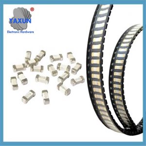 Gyors-lassú, gyorsszünet 6125 chip biztosíték 20A, 30A, 40A, új energia akkumulátorcsomag áramkör védelmére |
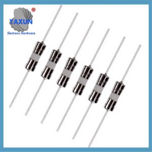
 Mikroellenállás típusú Pico miniatűr kazettás biztosíték, 250 V axiális vezetékkel, zöld, gyors hatású, gyors fújással |
 6×30, 6.3×32 gyors működésű biztosíték Cső 200mA-50A 500V, 600V, 750, 1000V |
én. Alapvető különbség
| Jellemzők | Gyorsan működő biztosíték | Lassú működésű biztosíték |
|---|---|---|
| Beégetési sebesség | Gyors válasz, gyors beolvadás túláram esetén (ezredmásodperces szint) | Válasz késése, rövid impulzusáramot képes ellenállni a biztosítékolás előtt |
| Túlfeszültség ellenállás | Gyenge, könnyen tévedésből felfújja a pillanatnyi nagy áram | Erős, képes elnyelni az energiát, hogy ellenálljon a túlfeszültségnek |
| Alkalmazható terhelési típus | Ellenállási terhelés (mint például a fűtőszál), érzékeny IC áramkör | Kapacitív/induktív terhelés (mint például a motor, kapcsolóüzemű tápegység) |
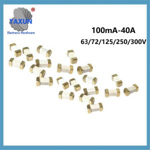 Gyors hatású, lassú működésű chip biztosítékok 63V 72V 125V 250V 300V új energia akkumulátorokhoz |
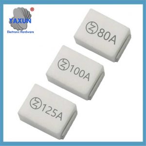 8810 nagyáramú chip biztosíték 20A-125A négyzet alakú kerámia biztosíték, lassan kioldó 32V ~ 125V |
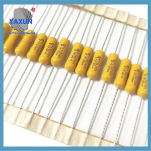
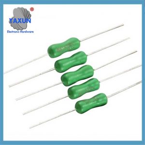 2.4-7mm-es axiális vezeték zöld/sárga biztosíték |
II.. Alkalmazási forgatókönyv
Gyors működésű biztosíték alkalmazható forgatókönyv
Ellenállásos áramkör stabil üzemi árammal (elektromos vízforraló, fűtőtest);
Áramkör, amelynek gyorsan meg kell védenie az értékes eszközöket (IC, MOS cső);
Érzékeny elektronikus berendezés túlfeszültség nélkül.
Lassan kiolvadó biztosíték alkalmazási forgatókönyvei
Kapacitív áramkörök indítási túlfeszültségekkel (kapcsolóüzemű tápegység elektrolitkondenzátorainak töltése);
Induktív terhelések nagy indítási áramokkal (motorok, kompresszorok);
Táp bemeneti/kimeneti csatlakozók és egyéb impulzusinterferenciára érzékeny kapcsolatok.
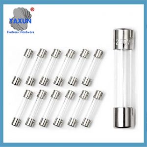
 6×30 kerámia biztosíték 500V/250V/125V 200mA-50A lassú fújás gyors fúj |
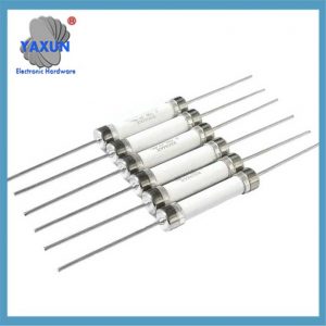 6×30, 6.35×32 nagyfeszültségű kerámia biztosítékcső 200mA-50A 500V, 600V, 750V, 1000V |
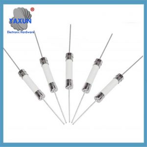
 Kerámia biztosíték 3×10, 3.6×10, 4x11 mm-es kerámia biztosítékcső 200mA-15A egytestes & ólomhuzallal |
III. Kiválasztási szempontok
Névleges áram: Általában 1.5-2 a berendezés maximális üzemi áramának szorzata, hogy kompatibilis legyen a túlfeszültségekkel.
A csere elve:
A Fast-break helyettesíthető lassú szünettel az interferencia elleni küzdelem javítása érdekében (kivéve az érzékeny áramköröket);
Soha ne cserélje le a lassú szünetet gyors szünetre, ellenkező esetben indítási biztosítékot okoz (például amikor a motor beindul).
A megkülönböztetés jelölése:
A gyors szünetet általában az F betű jelöli (Gyors hatású), a lassú szünetet pedig T jelöli (Idő-késleltetés).
IV. Műszaki elv
Lassú szünet késleltetési mechanizmus: Speciális struktúrákon keresztül nyelje el az energiát (mint például az ötvözetolvadékok), átmenetileg ellenáll az impulzusáramoknak (mint például a kondenzátor töltőáramok), és csak folyamatos túlterhelés esetén biztosítékot.
Gyors megszakítási mechanizmus: A biztosíték finom szerkezetű és érzékeny az áramváltozásokra, túláram esetén azonnal megszakad.
⚠️ Félreértés javítása: A lassú szünet nem azt jelenti “lassú válasz”, de megkülönböztetheti a hibás áramot és az impulzusáramot a hamis védelem elkerülése érdekében.