 English
 Afrikaans
 العربية
 বাংলা
বাংলা bosanski jezik
 Български
 Català
 粤语
粤语 中文(简体)
 中文(漢字)
 Hrvatski
 Čeština
 Nederlands
 Eesti keel
 Suomi
Suomi Français
 Deutsch
 Ελληνικά
 हिन्दी; हिंदी
 Magyar
 Bahasa Indonesia
 Italiano
 日本語
日本語 한국어
한국어 Latviešu valoda
 Lietuvių kalba
 македонски јазик
 Bahasa Melayu
 Norsk
Norsk پارسی
پارسی Polski
 Português
 Română
 Русский
 Cрпски језик
 Slovenčina
 Slovenščina
 Español
 Svenska
 ภาษาไทย
 Türkçe
 Українська
 اردو
اردو Tiếng Việt
A temperature acquisition circuit for a PT100 or PT1000 sensor probe typically consists of a stable current source to excite the sensor, a high-precision resistance measurement circuit to detect the change in resistance with temperature, and an analog-to-digital converter (ADC) to convert the measured voltage into a digital signal that can be processed by a microcontroller or data acquisition system; the key difference between a PT100 and PT1000 circuit is the scale of resistance values due to the Pt100 having a nominal resistance of 100 ohms at 0°C while a Pt1000 has 1000 oma na 0°C, often requiring adjustments in the measurement circuit depending on the desired accuracy and application.
The article introduces the resistance change of PT100 and PT1000 metal thermal resistor sensor probes at different temperatures, as well as a variety of temperature acquisition circuit solutions. Including resistance voltage division, bridge measurement, constant current source and AD623, AD620 acquisition circuit. In order to resist interference, especially electromagnetic interference in the aerospace field, an airborne PT1000 temperature sensor acquisition circuit design is proposed, including a T-type filter for filtering and improving measurement accuracy.
Abstract generated by CSDN through intelligent technology
 PT100 Temperature cable sensor for Precise temperature measurement in containers, tanks and pipes |
 Sonda temperaturnog senzora T100 kabl za visoku temperaturu -50~260 |
 PT100 platinum resistance temperature sensor for transmitter surface temperature |
PT100/PT1000 rješenje kruga za prikupljanje temperature
1. Temperature resistance change table of PT100 and PT1000 sensors
Metalni termički otpornici kao što je nikl, copper and platinum resistors have a positive correlation with the change of temperature. Platina ima najstabilnija fizička i hemijska svojstva i najčešće se koristi. Opseg mjerenja temperature najčešće korištenih sondi Pt100 senzora otpornosti na platinu je -200~850℃, i rasponi mjerenja temperature od Pt500, Pt1000 senzorske sonde, itd. sukcesivno se smanjuju. Pt1000, Raspon mjerenja temperature je -200~420℃. Prema međunarodnom standardu IEC751, temperaturne karakteristike platinskog otpornika Pt1000 ispunjavaju sljedeće zahtjeve:
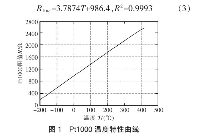
Pt1000 temperaturna karakteristična kriva
Prema krivulji temperaturne karakteristike Pt1000, the slope of the resistance characteristic curve changes slightly within the normal operating temperature range (kao što je prikazano na slici 1). The approximate relationship between resistance and temperature can be obtained through linear fitting:
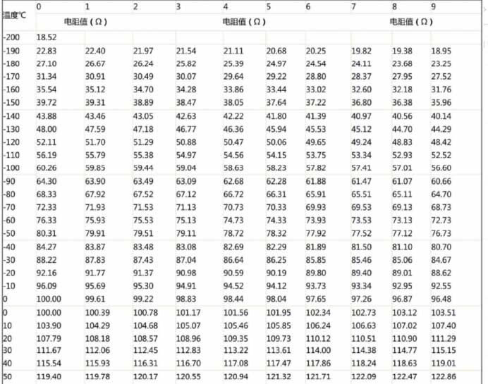
PT100 tablica promjene temperaturne otpornosti 1
2. Često korištena rješenja akvizicionih krugova
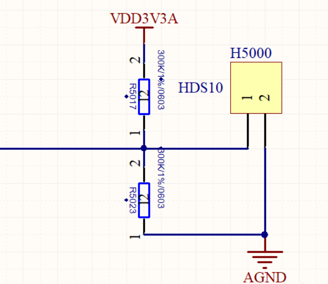
2. 1 Resistor voltage divider output 0~3.3V/3V analog voltage single chip AD port direct acquisition
Opseg izlaznog napona kruga za mjerenje temperature je 0~3.3V, PT1000 (Vrijednost otpora PT1000 se značajno mijenja, and the temperature measurement sensitivity is higher than PT100; PT100 je pogodniji za mjerenje temperature velikih razmjera).
Najjednostavniji način je korištenje metode podjele napona. The voltage is generated by the TL431 voltage reference source chip, which is a 4V voltage reference source. Alternativno, REF3140 can be used to generate 4.096V as a reference source. Reference source chips also include REF3120, 3125, 3130, 3133, i 3140. The chip uses a SOT-32 package and a 5V input voltage. Izlazni napon se može odabrati prema traženom referentnom naponu. Naravno, according to the normal voltage input range of the AD port of the microcontroller, ne može preći 3V/3.3V.
PT100 single chip AD port circuit direct acquisition
2.2 Resistor voltage division output 0~5V analog voltage, and the AD port of the microcontroller directly collects it.
Naravno, some circuits are powered by a 5V microcontroller, and the maximum operating current of the PT1000 is 0.5mA, so an appropriate resistance value must be used to ensure the normal operation of the component.
Na primjer, the 3.3V in the voltage division schematic diagram above is replaced by 5V. The advantage of this is that the 5V voltage division is more sensitive than the 3.3V voltage, and the collection is more accurate. Zapamti, teoretski izračunati izlazni napon ne može preći +5V. Inače, the microcontroller will be damaged.
2.3 Najčešće korišteno mjerenje mosta

The voltage divider circuit of PT100 outputs 0~5V analog voltage
Use R11, R12, R13 and Pt1000 to form a measurement bridge, gdje je R11=R13=10k, R12=1000R precision resistor. Kada vrijednost otpora Pt1000 nije jednaka vrijednosti otpora R12, the bridge will output a mV level voltage difference signal. Ovaj signal razlike napona se pojačava krugom pojačala instrumenta i daje željeni signal napona, which can be directly connected to the AD conversion chip or the AD port of the microcontroller.
Princip mjerenja otpora ovog kola:
1) PT1000 je termistor, and its resistance changes basically linearly with the change of temperature.
2) At 0 stepeni, otpor PT1000 je 1kΩ, tada su Ub i Ua jednaki, to jest, Uba = Ub – Do = 0.
3) Pod pretpostavkom da na određenoj temperaturi, otpor PT1000 je 1.5kΩ, tada Ub i Ua nisu jednaki. According to the voltage divider principle, we can find Uba = Ub – Uradi > 0.
4) OP07 je operaciono pojačalo, and its voltage amplification factor A depends on the external circuit, gdje je A = R2/R1 = 17.5.
5) Izlazni napon Uo od OP07 = Uba * A. Dakle, ako koristimo voltmetar za mjerenje izlaznog napona OP07, možemo zaključiti vrijednost Uab. Pošto je Ua poznata vrijednost, možemo dalje izračunati vrijednost Ub. Onda, using the voltage divider principle, možemo izračunati specifičnu vrijednost otpora PT1000. Ovaj proces se može postići softverskim proračunom.
6) Ako znamo vrijednost otpora PT1000 na bilo kojoj temperaturi, we only need to look up the table according to the resistance value to know the current temperature.
2.4 Izvor konstantne struje
Zbog efekta samozagrijavanja termičkog otpornika, it is necessary to ensure that the current flowing through the resistor is as small as possible, and generally the current is expected to be less than 10mA. Provjereno je da samozagrijavanje platinskog otpornika PT100 od 1 mW will cause a temperature change of 0.02 to 0.75℃, so reducing the current of the platinum resistor PT100 can also reduce its temperature change. Međutim, ako je struja premala, podložan je smetnjama buke, so it is generally taken at 0.5 to 2 mA, tako da je struja izvora konstantne struje odabrana kao izvor konstantne struje od 1mA.
The chip selected is the constant voltage source chip TL431, and then the current negative feedback is used to convert it into a constant current source. Krug je prikazan na slici:
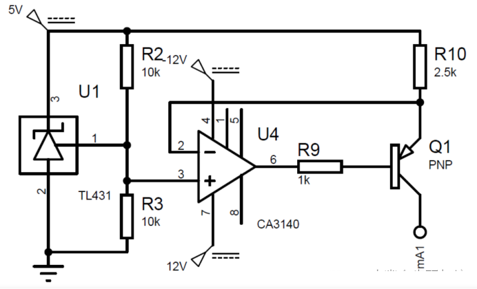
Constant current source of resistor PT100 circuit acquisition scheme
The operational amplifier CA3140 is used to improve the load capacity of the current source, a formula za izračunavanje izlazne struje je:
Insert picture description here The resistor should be a 0.1% precizni otpornik. Konačna izlazna struja je 0,996mA, to jest, tačnost je 0.4%.
Kolo izvora konstantne struje treba imati sljedeće karakteristike:
Temperaturna stabilnost: Budući da je naše okruženje za mjerenje temperature 0-100℃, izlaz strujnog izvora ne bi trebao biti osjetljiv na temperaturu. And TL431 has an extremely low temperature coefficient and low temperature drift.
Dobra regulacija opterećenja: Ako je strujna talasnost prevelika, to će uzrokovati greške u čitanju. Prema teorijskoj analizi. Since the input voltage varies between 100-138.5mV, a raspon mjerenja temperature je 0-100℃, tačnost mjerenja temperature je ±1 stepen Celzijusa, tako da bi se izlazni napon trebao promijeniti za 38,5/100=0,385mV za svaki porast temperature okoline za 1℃. Kako bi se osiguralo da fluktuacija struje ne utiče na točnost, razmotrite najekstremniji slučaj, at 100 stepeni Celzijusa, vrijednost otpora PT100 bi trebala biti 138,5R. Tada bi strujni talas trebao biti manji od 0,385/138,5=0,000278mA, to jest, the change in current during the load change should be less than 0.000278mA. U stvarnoj simulaciji, trenutni izvor ostaje u osnovi nepromijenjen.
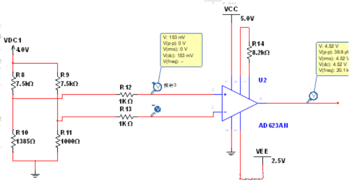
3. Rješenje AD623 akvizicionog kola
Princip se može odnositi na gornji princip mjerenja mosta.
Akvizicija na niskim temperaturama:
AD620 measures PT100 acquisition solution high temperature (150°)
Akvizicija visoke temperature
Insert picture description here
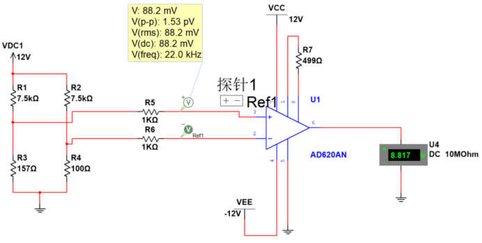
4. Rješenje akvizicionog kola AD620
AD620 PT100 acquisition solution for high temperature (150°):

AD620 measures PT100 acquisition solution at low temperature (-40°)
AD620 PT100 acquisition solution for low temperature (-40°):
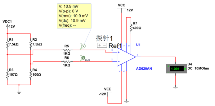
AD620 measures PT100 acquisition scheme at room temperature (20°)
AD620 PT100 acquisition solution for room temperature (20°):
PT100 sensor high temperature acquisition circuit
5. Anti-interference filtering analysis of PT100 and PT1000 sensors
Akvizicija temperature u nekom kompleksu, oštra ili posebna okruženja će biti podložna velikim smetnjama, uglavnom uključujući EMI i REI. Na primjer, u primjeni mjerenja temperature motora, high-frequency disturbances caused by motor control and high-speed rotation of the motor.
Postoji i veliki broj scenarija kontrole temperature unutar zrakoplovnih i svemirskih vozila, koji mjere i kontrolišu elektroenergetski sistem i sistem kontrole životne sredine. Srž kontrole temperature je mjerenje temperature. Budući da se otpor termistora može linearno mijenjati s temperaturom, korištenje otpornosti platine za mjerenje temperature je efikasna metoda mjerenja temperature visoke preciznosti. Glavni problemi su sljedeći:
1. Otpor na vodnoj žici se lako uvodi, što utiče na tačnost merenja senzora;
2. In certain strong electromagnetic interference environments, the interference may be converted into DC output offset error after being rectified by the instrument amplifier, utiče na tačnost merenja.
5.1 Vazdušni vazdušni PT1000 akvizicioni krug
Pogledajte dizajn zračnog PT1000 akvizicionog kruga za anti-elektromagnetne smetnje u određenom zrakoplovstvu.
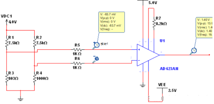
AD623 acquisition circuit scheme for PT100 sensor
Filter je postavljen na krajnjem kraju akvizicionog kruga. The PT1000 acquisition preprocessing circuit is suitable for anti-electromagnetic interference preprocessing of airborne electronic equipment interfaces; the specific circuit is:
Ulazni napon +15V se pretvara u visokoprecizni izvor napona +5V preko regulatora napona. The +5V high-precision voltage source is directly connected to the resistor R1, and the other end of the resistor R1 is divided into two paths. One is connected to the in-phase input end of the op amp, and the other is connected to the PT1000 resistor A end through the T-type filter S1. Izlaz operacijskog pojačala je povezan s invertirajućim ulazom kako bi se formirao sljedbenik napona, a invertni ulaz je spojen na uzemljenje regulatora napona kako bi se osiguralo da je napon na infaznom ulazu uvijek nula. Nakon prolaska kroz S2 filter, jedan kraj A otpornika PT1000 je podijeljen na dva puta, one through resistor R4 as the differential voltage input D, i jedan kroz otpornik R2 na AGND. Nakon prolaska kroz S3 filter, drugi kraj B otpornika PT1000 je podijeljen na dva puta, one through resistor R5 as the differential voltage input E, i jedan kroz otpornik R3 na AGND. D i E su povezani preko kondenzatora C3, D je spojen na AGND preko kondenzatora C1, a E je spojen na AGND preko kondenzatora C2. The precise resistance value of PT1000 can be calculated by measuring the differential voltage across D and E.
Ulazni napon +15V se pretvara u visokoprecizni izvor napona +5V preko regulatora napona. +5V je direktno spojen na R1. Drugi kraj R1 je podijeljen na dva puta, jedan spojen na in-fazni ulaz operativnog pojačala, and the other connected to the A end of the PT1000 resistor through the T-type filter S1. Izlaz operacijskog pojačala je povezan s invertirajućim ulazom kako bi se formirao sljedbenik napona, a invertni ulaz je spojen na uzemljenje regulatora napona kako bi se osiguralo da je napon na invertirajućem ulazu uvijek nula. U ovo vrijeme, struja koja teče kroz R1 je konstantna 0,5 mA. Regulator napona koristi AD586TQ/883B, a operacijsko pojačalo koristi OP467A.
Nakon prolaska kroz S2 filter, jedan kraj A otpornika PT1000 je podijeljen na dva puta, jedan kroz otpornik R4 kao kraj ulaza diferencijalnog napona D, i jedan kroz otpornik R2 na AGND. Nakon prolaska kroz S3 filter, drugi kraj B otpornika PT1000 je podijeljen na dva puta, jedan kroz otpornik R5 kao kraj ulaza diferencijalnog napona E, i jedan kroz otpornik R3 na AGND. D i E su povezani preko kondenzatora C3, D je spojen na AGND preko kondenzatora C1, a E je spojen na AGND preko kondenzatora C2.
Otpor R4 i R5 je 4,02 k oma, otpor R1 i R2 je 1M oma, kapacitivnost C1 i C2 je 1000pF, a kapacitivnost C3 je 0,047uF. R4, R5, C1, C2, i C3 zajedno čine mrežu RFI filtera. The RFI filter completes the low-pass filtering of the input signal, and the objects filtered out include the differential mode interference and common mode interference carried in the input differential signal. Izračun granične frekvencije -3dB smetnje zajedničkog moda i interferencije diferencijalnog moda koji se prenose u ulaznom signalu prikazan je u formuli:
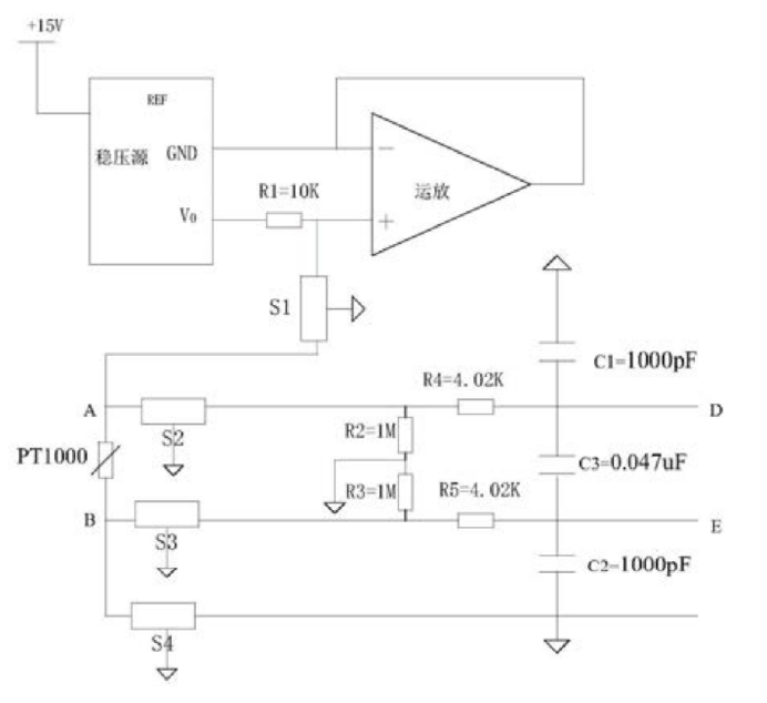
Vazdušni vazdušni PT1000 akvizicioni krug
Zamjena vrijednosti otpora u proračun, granična frekvencija zajedničkog moda je 40 kHz, a granična frekvencija diferencijalnog moda je 2.6KHZ.
Krajnja tačka B je povezana na AGND preko S4 filtera. Među njima, terminali uzemljenja filtera od S1 do S4 su svi povezani na zaštitno uzemljenje aviona. Budući da struja koja teče kroz PT1000 je poznatih 0,05mA, precizna vrijednost otpora PT1000 može se izračunati mjerenjem diferencijalnog napona na oba kraja D i E.
S1 do S4 koriste filtere tipa T, model GTL2012X‑103T801, with a cutoff frequency of M±20%. Ovaj sklop uvodi niskopropusne filtere u vanjske linije sučelja i izvodi RFI filtriranje na diferencijalnom naponu. Kao krug za prethodnu obradu za PT1000, efikasno eliminiše smetnje elektromagnetnog i RFI zračenja, što značajno poboljšava pouzdanost prikupljenih vrijednosti. Osim toga, napon se direktno meri sa oba kraja PT1000 otpornika, eliminisanje greške uzrokovane otporom elektrode i poboljšanje tačnosti vrednosti otpora.
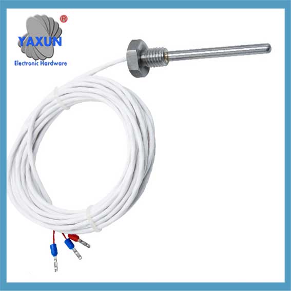 3-wire Class B high industrial temperature control PT100 platinum thermal resistor temperature sensor |
 K-E type compression spring thermocouple, pt100 temperature sensor probe |
 High precision PT100 temperature sensor for transformer temperature measurement |
5.2 Filter T-tipa
Insert picture description here
Filter T-tipa sastoji se od dva induktora i kondenzatora. Oba kraja imaju visoku impedanciju, i njegove performanse gubitka umetanja su slične onima kod filtera tipa π, ali nije sklona tome “zvoni” i može se koristiti u sklopnim krugovima.