 English
 Afrikaans
 العربية
 বাংলা
বাংলা bosanski jezik
 Български
 Català
 粤语
粤语 中文(简体)
 中文(漢字)
 Hrvatski
 Čeština
 Nederlands
 Eesti keel
 Suomi
Suomi Français
 Deutsch
 Ελληνικά
 हिन्दी; हिंदी
 Magyar
 Bahasa Indonesia
 Italiano
 日本語
日本語 한국어
한국어 Latviešu valoda
 Lietuvių kalba
 македонски јазик
 Bahasa Melayu
 Norsk
Norsk پارسی
پارسی Polski
 Português
 Română
 Русский
 Cрпски језик
 Slovenčina
 Slovenščina
 Español
 Svenska
 ภาษาไทย
 Türkçe
 Українська
 اردو
اردو Tiếng Việt
LTSpice simulation of 3-wire measurement scheme for PT100 (RTD) senzor: Pt100 is a thermal resistor temperature sensor, the full name is platinum resistor 100 ohms. It is made of pure platinum, and its resistance value increases linearly in a certain proportion when the temperature changes.
PT100, puni naziv platinskog termalnog otpornika, je otporni temperaturni senzor napravljen od platine (Pt), a njegova vrijednost otpora se mijenja sa temperaturom. The 100 nakon PT znači da je njegova vrijednost otpora 100 oma na 0℃, a njegova vrijednost otpora je oko 138.5 oma na 100℃. It has the characteristics of high precision, dobra stabilnost, jaka sposobnost protiv smetnji, and the relationship between its resistance and temperature change is: R=R0(1+αT), where α =0.00392, Ro is 100Ω (resistance value at 0℃), and T is Celsius temperature.

PT100 temperature resistance corresponding change table
2. Import pt100 resistor
Since there is no pt100 in the LTspice component library, we need to import pt100 manually. Since the spice file of pt100 is not found, we import the sliding resistor here as a substitute. To import the sliding resistor, morate dodati sljedeće tri datoteke u LTspice instalacijski direktorij. Kopirajte tri fajla (asc, asy i lib) odvojeno, kreirajte fajlove za svaki, i konačno ih stavite na odgovarajuću lokaciju LTSpice instalacije. Stavite asc sa drugim šemama, stavi asy u sym pod lib, i stavite lib u sub pod lib. Nakon dodavanja, možete vidjeti potenciometar u komponenti u LTSpice. Ovaj potenciometar je potreban klizni otpornik.
potenciometer_test.asc
Verzija 4
SHEET 1 880 680
WIRE 272 48 0 48
WIRE 528 48 272 48
WIRE 272 80 272 48
WIRE 528 80 528 48
WIRE 0 96 0 48
WIRE 0 192 0 176
WIRE 272 208 272 176
WIRE 528 208 528 176
ZASTAVA 272 208 0
ZASTAVA 0 192 0
ZASTAVA 320 128 out1
ZASTAVA 528 208 0
ZASTAVA 576 128 out2
SIMBOL napon 0 80 R0
SYMATTR InstName V1
SYMATTR vrijednost 10
SYMBOL potenciometar 272 176 M0
SYMATTR InstName U1
SYMATTR SpiceLine2 brisač=0.2
SYMBOL potenciometar 528 176 M0
SYMATTR InstName U2
SYMATTR SpiceLine R=1
SYMATTR SpiceLine2 brisač=0.8
TEKST 140 228 lijevo 2 !.op
potenciometer.asy
Verzija 4
SymbolType BLOCK
LINE Normalno 16 -31 -15 -16
LINE Normalno -16 -48 16 -31
LINE Normalno 16 -64 -16 -48
LINE Normalno 1 -9 -15 -16
LINE Normalno 1 0 1 -9
LINE Normalno 1 -94 1 -87
LINE Normalno -24 -56 -16 -48
LINE Normalno -24 -40 -15 -48
LINE Normalno -47 -48 -15 -48
LINE Normalno -16 -80 16 -64
LINE Normalno 1 -87 -16 -80
PROZOR 0 30 -90 lijevo 2
PROZOR 39 30 -50 lijevo 2
PROZOR 40 31 -23 lijevo 2
SYMATTR prefiks X
SYMATTR ModelFile potentiometer.lib
SYMATTR SpiceLine R=1k
SYMATTR SpiceLine2 brisač=0,5
SYMATTR Value2 potentiometer
PIN 0 -96 NONE 8
PINATTR PinName 1
PINATTR SpiceOrder 1
PIN 0 0 NONE 8
PINATTR PinName 2
PINATTR SpiceOrder 2
PIN -48 -48 NONE 8
PINATTR PinName 3
PINATTR SpiceOrder 3
potentiometer.lib
* This is the potentiometer
* _____
* 1–|_____|–2
* |
* 3
*
.SUBCKT potentiometer 1 2 3
.param w=limit(wiper,1m,.999)
R0 1 3 {R*(1-w)}
R1 3 2 {R*(w)}
.ENDS
3. Wheatstone bridge to measure PT100 resistance
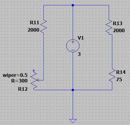
Povezivanje Wheatstoneovog mosta i LTspice simulacijski model
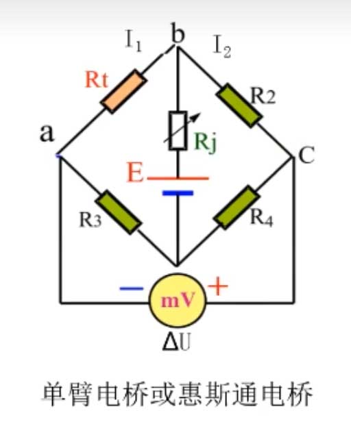
Single-arm bridge or Wheatstone circuit
Povezivanje Wheatstoneovog mosta i LTspice simulacijski model:
Kada je most izbalansiran, the voltage meter measurement value eq?%5CbigtriangleupU=0
I1*Rt=I2*R2
I1*R3=I2*R4
Od ovoga, it can be deduced that: Rt/R3=R2/R4
To je: Rt*R4=R2*R3
The resistance measurement result in this way has nothing to do with the accuracy of the voltage meter, the accuracy of the resistance, and the electromotive force. It avoids the error caused by the change of the power supply over time, and avoids the problem of ammeter voltage division, voltage meter shunt, and too many wire voltage division.
Different measurement methods of PT100:
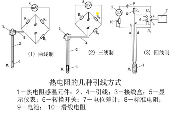
Several Leading Methods of P Thermal Resistor
Kada je tačka temperature koja se meri na licu mesta daleko od instrumenta, potrebno je termički otpornik spojiti olovnom žicom. Otpor elektrode je r. Dvožični sistem ne može izbjeći grešku uzrokovanu otporom žice tokom proračuna, a stvarna izmjerena vrijednost otpora će biti manja.
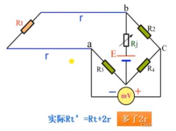
Otpor termičkog otpornika plus olovne žice je r
Da bi se otklonila greška, uvodi se četverožična veza. Kada se Rt poveća za 2r, R2 se takođe povećava za 2r. Bez obzira koliko je duga žica, most se može izbalansirati. Potrebno je izvući četiri žice. Pošto su naponi u tačkama p i q jednaki, mogu biti ekvivalentne jednoj tački, što je trožični način povezivanja, to jest, metoda trožilnog povezivanja simulirana u ovom eksperimentu. U praksi, trožični se također najčešće koristi, uzimajući u obzir i ekonomičnost i tačnost.
4. Trožilno mjerenje LTSpice simulacija
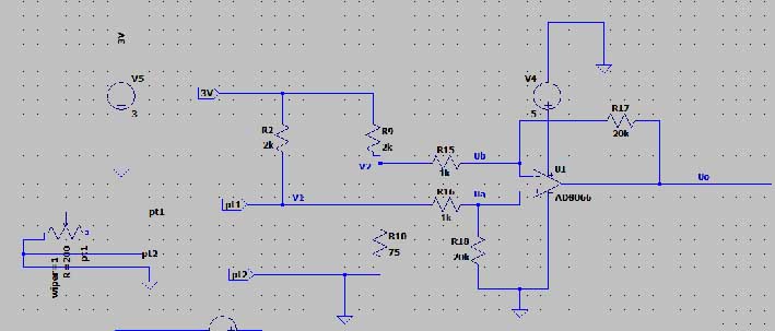
3-merenje žice, i spojite krug op-amp na izlaz
Ovaj eksperiment koristi trožilno mjerenje, i povezuje krug operacijskog pojačala na izlazni dio kako bi pojačao izlazni signal radi lakšeg mjerenja.
Uo= (V1-V2)*(R17/R15)=20*(V1-V2)
To je, V1=(Uo+20*V2)/20
Prema podjeli napona otpornika:
V1 = Vs*(Rt/(R2+Rt))
V2 = Vs*(R10/(R9+R10))
Ulazni napon ove simulacije je 3V. Nakon obračuna, V2≈108,434mV
V1=(Uo+2168.68)/20
V1=Rt/(R7+Rpt) *3000
Dakle: Rt=2000V1/(3000-V1)
Rt je odgovarajuća vrijednost otpora PT100. Odgovarajuća vrijednost temperature može se dobiti pregledom tabele.
Podesite otpor kliznog reostata (Rt) to 130.6 oma za temperaturu od 78 stepeni Celzijusa, pročitaj V1, V2, i Uo za izračunavanje Rt.
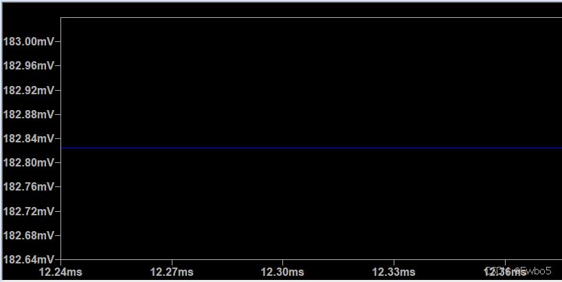
Rt je odgovarajuća vrijednost otpora PT100, odgovarajuća vrednost temperature
V1 is about 182.82mV, V2 is about 118.46mV, and U0 is about 1.39V. The calculated Rpt is about 129.78V. The table shows that the temperature read is 76 stepeni Celzijusa, which is close.
Podesite otpor kliznog reostata (Rt) to 200.05 oma za temperaturu od 266.5 stepeni Celzijusa, pročitaj V1, V2, i Uo za izračunavanje Rt.
V1 is about 270.45mV, V2 is about 118.46mV, and U0 is about 3.0257V. The calculated Rpt is about 198.16V, and the error value is about 1%. The table shows that the temperature read is 261.3 stepeni Celzijusa, with an error of about 1%.
The temperature measurement principle of the three-wire PT100 is mainly based on the bridge method. The measurement circuit is usually an unbalanced bridge, and the PT100 is used as a bridge arm resistor of the bridge. When current passes through the PT100, the change in its resistance value will cause the change in the output voltage of the bridge. By measuring this output voltage, the resistance value of the PT100 can be calculated, and then the measured temperature can be obtained.
In order to eliminate the influence of lead resistance, the three-wire PT100 adopts a special design, connecting one wire to the power supply end of the bridge, and the other two wires are connected to the bridge arm where the PT100 is located and the bridge arm adjacent to it. Na ovaj način, both bridge arms introduce lead resistances of the same resistance value, so that the bridge is in a balanced state. Stoga, the change in lead resistance has no effect on the measurement result. Međutim, there will still be influences such as devices in actual measurement. The measured resistance value is not accurate. In order to eliminate this error, some compensation can be added when reading.