Категорії продуктів
- термічний запобіжник 32
- Поверхневе кріплення 12
- термістор 36
- Власник запобіжника кріплення на друковці 27
- Проводка 6
- Власники запобіжників леза 17
- термостат 50
- Електричний запобіжник 24
- Автомобільний датчик температури 7
- Термічний вимикач 22
- Власник коробки 36
- Датчик температури 75
- Тепловий перемикач 68
- Забій 20
- Боллт вниз по запору 8
Теги продукту
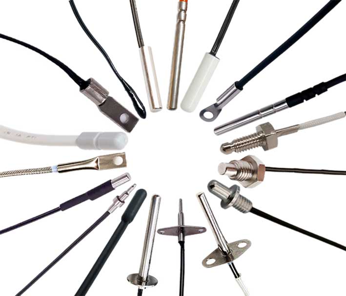
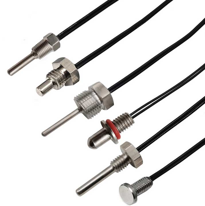
Зонд датчика DS18B20
Характеристики датчика температури DS18B20: водонепроникний, антикорозійний.
Деталі упаковки: можна налаштувати за потреби. MAXIM імпортний в оригінальній упаковці; Пакет ТО-92; велика кількість на складі. І надайте цифровий датчик температури DS18B20 у водонепроникному корпусі з трубки з нержавіючої сталі.
The ds18b20 temperature sensor probe has high accuracy. The temperature measurement accuracy can reach 0.01℃, and the temperature measurement accuracy in the wide temperature range is 0.1℃. Good stability and high precision in mass production.
The DS18B20 digital sensor probe and cable are easy to connect and can be used in a variety of situations after being packaged. Such as stainless steel straight pipe type, різьбового типу, магнітний адсорбційний тип, різні моделі, включаючи LTM8877, LTM8874 тощо.
DS18B20 — широко використовуваний цифровий датчик температури. It outputs a digital signal and has the characteristics of small size, Низький апаратне забезпечення, strong anti-interference ability and high accuracy. Його зовнішній вигляд в основному змінюється залежно від програми. Інкапсульований DS18B20 можна використовувати для вимірювання температури кабелю, вимірювання температури циркуляції доменної води, вимірювання температури котла, machine room temperature measurement, вимірювання температури сільськогосподарської теплиці, вимірювання температури чистого приміщення, вимірювання температури на складах боєприпасів та інші випадки, пов’язані з обмеженням температури. Зносостійкий і ударостійкий, невеликі за розміром, простий у використанні, з різними формами упаковки, він підходить для цифрового вимірювання температури та контролю різного невеликого космічного обладнання.
Main features of DS18B20 sensor probe
1. Основні характеристики DS18B20
1.1. The adaptable voltage range is wider, діапазон напруги: 3.0~5.5V, and can be powered by the data line in parasitic power mode
1.2. Унікальний метод однопровідного інтерфейсу. При підключенні DS18B20 до мікропроцесора, йому потрібна лише одна лінія порту для досягнення двостороннього зв’язку між мікропроцесором і DS18B20.
1.3. DS18B20 supports multi-point networking function. Multiple DS18B20 can be connected in parallel on the only three lines to achieve multi-point temperature measurement.
1.4. DS18B20 does not require any external components during use. All sensing components and conversion circuits are integrated into an integrated circuit shaped like a triode.
1.5. Temperature range -55℃~+125℃, accuracy is ±0.5℃ at -10~+85℃
1.6. The programmable resolution is 9~12 bits, and the corresponding resolvable temperatures are 0.5℃, 0.25℃, 0.125℃ and 0.0625℃ respectively, which can achieve high-precision temperature measurement.
1.7. At 9-bit resolution, the temperature can be converted into numbers in up to 93.75ms. At 12-bit resolution, the temperature value can be converted into numbers in up to 750ms, which is faster.
1.8. The measurement results directly output digital temperature signals and are serially transmitted to the CPU via the "one-line bus". В той же час, the CRC check code can be transmitted, which has strong anti-interference and error correction capabilities.
1.9. Negative voltage characteristics: When the polarity of the power supply is reversed, the chip will not be burned due to heat, but it will not work properly.
2. Appearance and internal structure of DS18B20 sensor
The internal structure of the DS18B20 sensor mainly consists of four parts: 64-розрядна фотолітографія ROM, датчик температури, енергонезалежний сигнал тривоги температури TH і TL, and configuration register.
The appearance and pin arrangement of DS18B20 are as follows:
Визначення контакту DS18B20:
(1) DQ — це термінал введення/виведення цифрового сигналу;
(2) GND є заземленням;
(3) VDD is the input terminal of the external power supply (grounded in the parasitic power wiring mode).
3. Working principle of DS18B20
The reading and writing timing and temperature measurement principle of DS18B20 are the same as those of DS1820, except that the number of digits of the temperature value obtained is different due to different resolutions, а час затримки під час перетворення температури зменшено з 2 с до 750 мс. The oscillation rate of high temperature coefficient crystal oscillator changes significantly with temperature changes, а згенерований сигнал використовується як імпульсний вхід лічильника 2. Лічильник 1 і температурний регістр попередньо встановлено на базове значення, що відповідає -55°C. Лічильник 1 відраховує імпульсний сигнал, створений кварцевим генератором з низьким температурним коефіцієнтом. Коли встановлене значення лічильника 1 зменшується до 0, значення температурного регістра буде збільшено на 1, попередньо встановлене значення лічильника 1 буде перезавантажено, і лічильник 1 перезапустить підрахунок імпульсних сигналів, створених кристалічним генератором з низьким температурним коефіцієнтом. Цей цикл триває до лічильника 2 зараховує до 0, потім припиняє накопичувати значення регістра температури. В цей час, значення в реєстрі температури є виміряною температурою. The slope accumulator in Figure 3 is used to compensate and correct the nonlinearity in the temperature measurement process, і його вихід використовується для корекції попередньо встановленого значення лічильника 1.

ds18b20 sensor with accuracy up to 0.01℃

Індивідуальний зонд і кабель датчика ds18b20
DS18B20 has 4 main data components:
(1) The 64-bit serial number in the photoetched ROM is photoetched before leaving the factory. It can be regarded as the address serial code of the DS18B20. The arrangement of the 64-bit photolithography ROM is: перший 8 шматочки (28H) are the product type number, and the next 48 bits are the serial number of the DS18B20 itself. The last 8 bits are the cyclic redundancy check code of the previous 56 шматочки (CRC=X8+X5+X4+1). The function of photolithography ROM is to make each DS18B20 different, так що кілька DS18B20 можна підключити до однієї шини.
(2) The temperature sensor in DS18B20 can complete the measurement of temperature. Take 12-bit conversion as an example: it is provided in the form of 16-bit sign-extended two's complement reading, expressed in the form of 0.0625°C/LSB, де S - знаковий біт.
This is the 12-bit data obtained after 12-bit conversion, which is stored in two 8-bit RAMs of 18B20. Перший 5 bits in binary are the sign bits. Якщо виміряна температура перевищує 0, ці 5 біти є 0. Просто помножте виміряне значення на 0.0625 щоб отримати фактичну температуру. Якщо температура нижче ніж 0, ці 5 біти є 1, and the measured value needs to be inverted, plus 1, а потім помножити на 0.0625 щоб отримати фактичну температуру. Наприклад, цифровий вихід +125 ℃ становить 07D0H, цифровий вихід +25,0625 ℃ становить 0191H, the digital output of -25.0625℃ is FE6FH, і цифровий вихід -55 ℃ є FC90H.
(3) DS18B20 temperature sensor memory DS18B20. The internal memory of the temperature sensor includes a high-speed scratchpad RAM and a non-volatile electrically erasable EEPRAM, which stores the high-temperature and low-temperature flip-flops TH, TL and structural registers.
(4) Configuration register The meaning of each bit of this byte is as follows:
Таблиця 3: Configuration register structure
The lower five bits are always "1", and TM is the test mode bit, which is used to set whether the DS18B20 is in working mode or test mode. This bit is set to 0 when DS18B20 leaves the factory, and users should not change it. R1 and R0 are used to set the resolution, as shown in the following table: (DS18B20 is set to 12 біт при відвантаженні з заводу)
Таблиця 4: Temperature resolution setting table
4. High-speed temporary storage memory The high-speed temporary storage memory consists of 9 байтів, and its allocation is shown in Table 5. When the temperature conversion command is issued, the converted temperature value is stored in the 0th and 1st bytes of the cache memory in two-byte complement form. The microcontroller can read this data through the single-wire interface. When reading, the low bit is in front and the high bit is in the back. The data format is shown in Table 1. Corresponding temperature calculation: When the sign bit S=0, directly convert the binary bit to decimal; when S=1, first convert the complement to the original code, and then calculate the decimal value. Таблиця 2 shows some of the corresponding temperature values. The ninth byte is the redundancy check byte.
Таблиця 5: DS18B20 temporary register distribution
According to the communication protocol of DS18B20, the host (single chip microcomputer) must go through three steps to control DS18B20 to complete temperature conversion: DS18B20 must be reset before each read and write. After the reset is successful, a ROM command is sent, and finally a RAM command is sent, so that the predetermined operation can be performed on the DS18B20. Reset requires the main CPU to pull the data line down for 500 microseconds and then release it. When DS18B20 receives the signal, it waits for about 16 до 60 microseconds, and then sends out a low pulse of 60 до 240 microseconds. The main CPU receives this signal to indicate successful reset.
Таблиця 6: ROM instruction list
Зв’яжіться з нами
Чекаючи вашого електронного листа, Ми відповімо вам всередині 12 години з цінною інформацією, яка вам потрібна.
 English
 Afrikaans
 العربية
 বাংলা
বাংলা bosanski jezik
 Български
 Català
 粤语
粤语 中文(简体)
 中文(漢字)
 Hrvatski
 Čeština
 Nederlands
 Eesti keel
 Suomi
Suomi Français
 Deutsch
 Ελληνικά
 हिन्दी; हिंदी
 Magyar
 Bahasa Indonesia
 Italiano
 日本語
日本語 한국어
한국어 Latviešu valoda
 Lietuvių kalba
 македонски јазик
 Bahasa Melayu
 Norsk
Norsk پارسی
پارسی Polski
 Português
 Română
 Русский
 Cрпски језик
 Slovenčina
 Slovenščina
 Español
 Svenska
 ภาษาไทย
 Türkçe
 Українська
 اردو
اردو Tiếng Việt

