 English
 Afrikaans
 العربية
 বাংলা
বাংলা bosanski jezik
 Български
 Català
 粤语
粤语 中文(简体)
 中文(漢字)
 Hrvatski
 Čeština
 Nederlands
 Eesti keel
 Suomi
Suomi Français
 Deutsch
 Ελληνικά
 हिन्दी; हिंदी
 Magyar
 Bahasa Indonesia
 Italiano
 日本語
日本語 한국어
한국어 Latviešu valoda
 Lietuvių kalba
 македонски јазик
 Bahasa Melayu
 Norsk
Norsk پارسی
پارسی Polski
 Português
 Română
 Русский
 Cрпски језик
 Slovenčina
 Slovenščina
 Español
 Svenska
 ภาษาไทย
 Türkçe
 Українська
 اردو
اردو Tiếng Việt
วงจรการรับอุณหภูมิสำหรับหัวเซนเซอร์ PT100 หรือ PT1000 โดยทั่วไปจะประกอบด้วยแหล่งกำเนิดกระแสที่เสถียรเพื่อกระตุ้นเซ็นเซอร์, วงจรวัดความต้านทานที่มีความแม่นยำสูงเพื่อตรวจจับการเปลี่ยนแปลงความต้านทานตามอุณหภูมิ, และตัวแปลงอนาล็อกเป็นดิจิทัล (ADC) เพื่อแปลงแรงดันไฟฟ้าที่วัดได้ให้เป็นสัญญาณดิจิทัลที่สามารถประมวลผลได้ด้วยไมโครคอนโทรลเลอร์หรือระบบเก็บข้อมูล; ข้อแตกต่างที่สำคัญระหว่างวงจร PT100 และ PT1000 คือขนาดของค่าความต้านทาน เนื่องจาก Pt100 มีความต้านทานเล็กน้อยเป็น 100 โอห์มที่ 0°C ในขณะที่ Pt1000 มี 1000 โอห์มที่ 0°C, มักต้องมีการปรับวงจรการวัดขึ้นอยู่กับความแม่นยำและการใช้งานที่ต้องการ.
บทความนี้จะแนะนำการเปลี่ยนแปลงความต้านทานของโพรบเซ็นเซอร์ตัวต้านทานความร้อนโลหะ PT100 และ PT1000 ที่อุณหภูมิต่างกัน, รวมถึงโซลูชั่นวงจรการรับอุณหภูมิที่หลากหลาย. รวมถึงการแบ่งแรงดันความต้านทาน, การวัดสะพาน, แหล่งจ่ายกระแสคงที่และ AD623, วงจรการเข้าซื้อกิจการ AD620. เพื่อต้านทานการรบกวน, โดยเฉพาะการรบกวนทางแม่เหล็กไฟฟ้าในสนามการบินและอวกาศ, เสนอการออกแบบวงจรการรับเซ็นเซอร์อุณหภูมิ PT1000 ในอากาศ, รวมถึงตัวกรองชนิด T สำหรับการกรองและปรับปรุงความแม่นยำในการวัด.
บทคัดย่อที่สร้างโดย CSDN ผ่านเทคโนโลยีอัจฉริยะ
 เซ็นเซอร์สายเคเบิลอุณหภูมิ PT100 เพื่อการวัดอุณหภูมิในภาชนะที่แม่นยำ, ถังและท่อ |
 หัววัดอุณหภูมิเซนเซอร์ T100 อุณหภูมิสูง -50~260 สายเคเบิล |
 เซ็นเซอร์อุณหภูมิความต้านทานแพลทินัม PT100 สำหรับอุณหภูมิพื้นผิวเครื่องส่งสัญญาณ |
โซลูชันวงจรการซื้ออุณหภูมิ PT100/PT1000
1. ตารางการเปลี่ยนแปลงความต้านทานอุณหภูมิของเซ็นเซอร์ PT100 และ PT1000
ตัวต้านทานความร้อนที่เป็นโลหะ เช่น นิกเกิล, ตัวต้านทานทองแดงและแพลตตินัมมีความสัมพันธ์เชิงบวกกับการเปลี่ยนแปลงของอุณหภูมิ. แพลตตินัมมีคุณสมบัติทางกายภาพและเคมีที่เสถียรที่สุดและมีการใช้กันอย่างแพร่หลายมากที่สุด. ช่วงการวัดอุณหภูมิของหัวเซนเซอร์ Pt100 ความต้านทานแพลทินัมที่ใช้กันทั่วไปคือ -200~850°C, และช่วงการวัดอุณหภูมิ Pt500, หัวเซนเซอร์ Pt1000, ฯลฯ. จะลดลงเรื่อยๆ. พอต1000, ช่วงการวัดอุณหภูมิคือ -200~420℃. ตามมาตรฐานสากล IEC751, คุณลักษณะอุณหภูมิของตัวต้านทานแพลทินัม Pt1000 ตรงตามข้อกำหนดต่อไปนี้:
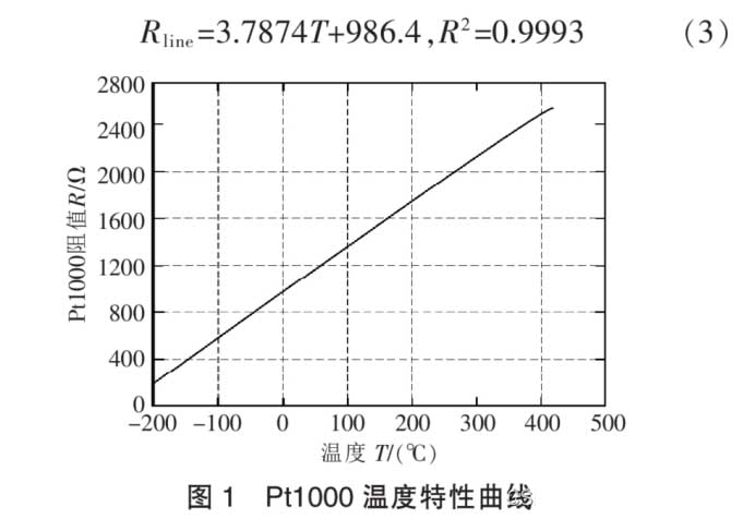
เส้นโค้งลักษณะอุณหภูมิ PT1000
ตามเส้นโค้งลักษณะอุณหภูมิ PT1000, ความชันของเส้นโค้งลักษณะความต้านทานเปลี่ยนแปลงเล็กน้อยภายในช่วงอุณหภูมิการทำงานปกติ (ดังแสดงในรูป 1). ความสัมพันธ์โดยประมาณระหว่างความต้านทานและอุณหภูมิสามารถหาได้จากข้อต่อเชิงเส้น:
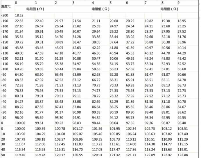
ตารางการเปลี่ยนแปลงความต้านทานอุณหภูมิ PT100 1
2. โซลูชั่นการซื้อกิจการที่ใช้กันทั่วไป
2. 1 ตัวต้านทานแรงดันไฟฟ้าแบ่งเอาต์พุต 0 ~ 3.3V/3V Analog แรงดันไฟฟ้าชิปเดี่ยว AD พอร์ต Direct Acquisition
ช่วงการวัดอุณหภูมิวงจรแรงดันเอาต์พุตคือ 0 ~ 3.3V, พีที1000 (ค่าความต้านทาน PT1000 มีการเปลี่ยนแปลงอย่างมาก, และความไวในการวัดอุณหภูมิสูงกว่า PT100; PT100 เหมาะสำหรับการวัดอุณหภูมิขนาดใหญ่).
วิธีที่ง่ายที่สุดคือการใช้วิธีการแบ่งแรงดันไฟฟ้า. แรงดันไฟฟ้าถูกสร้างขึ้นโดยชิปแหล่งอ้างอิงแรงดันไฟฟ้า TL431, ซึ่งเป็นแหล่งอ้างอิงแรงดันไฟ 4V. อีกทางหนึ่ง, REF3140 สามารถใช้เพื่อสร้าง 4.096V เป็นแหล่งอ้างอิง. ชิปแหล่งอ้างอิงยังรวมถึง REF3120 ด้วย, 3125, 3130, 3133, และ 3140. ชิปใช้แพ็คเกจ SOT-32 และแรงดันไฟฟ้าอินพุต 5V. แรงดันเอาต์พุตสามารถเลือกได้ตามแรงดันอ้างอิงที่ต้องการ. แน่นอน, ตามช่วงอินพุตแรงดันไฟฟ้าปกติของพอร์ต AD ของไมโครคอนโทรลเลอร์, ไม่เกิน 3V/3.3V.
PT100 ชิปตัวเดียว AD วงจรพอร์ตการเข้าซื้อกิจการโดยตรง
2.2 ตัวต้านทานแรงดันไฟฟ้าแบ่งเอาต์พุต 0 ~ 5V แรงดันไฟฟ้าแบบอะนาล็อก, และพอร์ต AD ของไมโครคอนโทรลเลอร์จะรวบรวมโดยตรง.
แน่นอน, วงจรบางวงจรใช้พลังงานจากไมโครคอนโทรลเลอร์ 5V, และกระแสไฟทำงานสูงสุดของ PT1000 คือ 0.5mA, ดังนั้นจึงต้องใช้ค่าความต้านทานที่เหมาะสมเพื่อให้แน่ใจว่าส่วนประกอบทำงานได้ตามปกติ.
ตัวอย่างเช่น, 3.3V ในแผนภาพการแบ่งแรงดันไฟฟ้าด้านบนถูกแทนที่ด้วย 5V. ข้อดีของสิ่งนี้คือการแบ่งแรงดันไฟฟ้า 5V มีความไวมากกว่าแรงดันไฟฟ้า 3.3V, และการรวบรวมมีความแม่นยำมากขึ้น. จดจำ, แรงดันเอาต์พุตที่คำนวณทางทฤษฎีไม่เกิน +5V. มิฉะนั้น, ไมโครคอนโทรลเลอร์จะเสียหาย.
2.3 การวัดสะพานที่ใช้กันมากที่สุด

วงจรแบ่งแรงดันไฟฟ้าของ PT100 เอาต์พุตแรงดันไฟฟ้าอะนาล็อก 0 ~ 5V
ใช้ R11, R12, R13 และ Pt1000 เพื่อสร้างสะพานวัด, โดยที่ r11 = r13 = 10k, R12=ตัวต้านทานความแม่นยำ 1,000R. เมื่อค่าความต้านทานของ PT1000 ไม่เท่ากับค่าความต้านทานของ R12, สะพานจะส่งสัญญาณความต่างศักย์ไฟฟ้าระดับ mV. สัญญาณความแตกต่างของแรงดันไฟฟ้านี้ถูกขยายโดยวงจรแอมพลิฟายเออร์เครื่องมือและส่งสัญญาณแรงดันไฟฟ้าที่ต้องการ, ซึ่งสามารถเชื่อมต่อโดยตรงกับชิปแปลง AD หรือพอร์ต AD ของไมโครคอนโทรลเลอร์.
หลักการวัดความต้านทานของวงจรนี้:
1) PT1000 เป็นเทอร์มิสเตอร์, และความต้านทานของมันจะเปลี่ยนแปลงโดยพื้นฐานเป็นเส้นตรงตามการเปลี่ยนแปลงของอุณหภูมิ.
2) ที่ 0 องศา, ความต้านทานของ PT1000 คือ1KΩ, จากนั้น ub และ ua เท่ากัน, นั่นคือ, uba = ub – ทำ = 0.
3) สมมติว่าในอุณหภูมิที่กำหนด, ความต้านทานของ PT1000 คือ1.5kΩ, จากนั้น UB และ UA ไม่เท่ากัน. ตามหลักการแบ่งแรงดันไฟฟ้า, เราจะหา Uba = Ub ได้ – ทำ > 0.
4) OP07 เป็นเครื่องขยายเสียงในการดำเนินงาน, และปัจจัยการขยายแรงดันไฟฟ้า A ขึ้นอยู่กับวงจรภายนอก, โดยที่ a = r2/r1 = 17.5.
5) แรงดันเอาต์พุต UO ของ OP07 = UBA * ก. ดังนั้นหากเราใช้โวลต์มิเตอร์เพื่อวัดแรงดันเอาต์พุตของ OP07, เราสามารถอนุมานคุณค่าของ UAB ได้. เนื่องจาก UA เป็นค่าที่ทราบ, เราสามารถคำนวณค่า UB เพิ่มเติมได้. แล้ว, โดยใช้หลักการแบ่งแรงดันไฟฟ้า, เราสามารถคำนวณค่าความต้านทานเฉพาะของ PT1000. กระบวนการนี้สามารถทำได้ผ่านการคำนวณซอฟต์แวร์.
6) หากเรารู้ค่าความต้านทานของ PT1000 ที่อุณหภูมิใด ๆ, เราแค่ต้องค้นหาตารางตามค่าความต้านทานเพื่อทราบอุณหภูมิปัจจุบัน.
2.4 แหล่งกระแสไฟฟ้าคงที่
เนื่องจากเอฟเฟกต์ความร้อนด้วยตนเองของตัวต้านทานความร้อน, จำเป็นต้องตรวจสอบให้แน่ใจว่ากระแสที่ไหลผ่านตัวต้านทานมีขนาดเล็กที่สุดเท่าที่จะเป็นไปได้, และโดยทั่วไปกระแสคาดว่าจะน้อยกว่า 10mA. ได้รับการตรวจสอบแล้วว่าการให้ความร้อนด้วยตนเองของตัวต้านทานแพลตตินัม PT100 ของ 1 mW จะทำให้เกิดการเปลี่ยนแปลงอุณหภูมิของ 0.02 ถึง 0.75 ℃, ดังนั้นการลดกระแสของตัวต้านทานแพลทินัม PT100 จึงสามารถลดการเปลี่ยนแปลงอุณหภูมิได้เช่นกัน. อย่างไรก็ตาม, ถ้ากระแสมีขนาดเล็กเกินไป, มันไวต่อการรบกวนเสียงรบกวน, โดยทั่วไปจึงนำไปที่ 0.5 ถึง 2 มิลลิแอมป์, ดังนั้นกระแสกระแสไฟฟ้าคงที่กระแสไฟฟ้าจะถูกเลือกเป็นแหล่งกระแสคงที่ 1mA.
ชิปที่เลือกคือชิปแหล่งจ่ายแรงดันคงที่ TL431, จากนั้นผลป้อนกลับเชิงลบในปัจจุบันจะถูกนำมาใช้เพื่อแปลงเป็นแหล่งกระแสคงที่. วงจรแสดงในรูป:
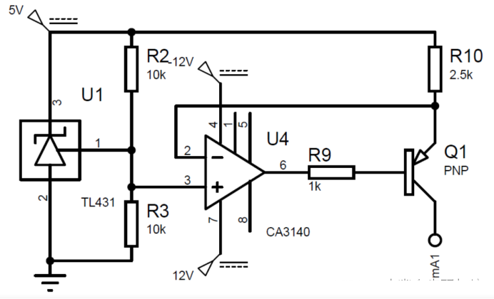
แหล่งจ่ายกระแสคงที่ของวงจรการซื้อวงจรตัวต้านทาน PT100
แอมพลิฟายเออร์สำหรับการดำเนินงาน CA3140 ใช้เพื่อปรับปรุงความสามารถในการรับน้ำหนักของแหล่งจ่ายกระแสไฟ, และสูตรการคำนวณสำหรับกระแสเอาต์พุตคือ:
ใส่คำอธิบายรูปภาพที่นี่ ตัวต้านทานควรเป็น a 0.1% ตัวต้านทานความแม่นยำ. กระแสไฟสุดท้ายคือ 0.996ma, นั่นคือ, ความแม่นยำคือ 0.4%.
วงจรแหล่งจ่ายกระแสคงที่ควรมีลักษณะดังต่อไปนี้:
ความเสถียรของอุณหภูมิ: เนื่องจากสภาพแวดล้อมการวัดอุณหภูมิของเราคือ 0-100℃, เอาต์พุตของแหล่งจ่ายกระแสไม่ควรไวต่ออุณหภูมิ. และ TL431 มีค่าสัมประสิทธิ์อุณหภูมิต่ำมากและการเบี่ยงเบนของอุณหภูมิต่ำ.
การควบคุมโหลดที่ดี: หากระลอกปัจจุบันมีขนาดใหญ่เกินไป, มันจะทำให้เกิดข้อผิดพลาดในการอ่าน. ตามการวิเคราะห์ทางทฤษฎี. เนื่องจากแรงดันไฟฟ้าขาเข้าแตกต่างกันไประหว่าง 100-138.5mV, และช่วงการวัดอุณหภูมิคือ 0-100 ℃, ความแม่นยำในการวัดอุณหภูมิอยู่ที่ ±1 องศาเซลเซียส, ดังนั้นแรงดันไฟขาออกควรเปลี่ยนแปลง 38.5/100=0.385mV สำหรับอุณหภูมิแวดล้อมที่เพิ่มขึ้นทุกๆ 1°C. เพื่อให้มั่นใจว่าความผันผวนในปัจจุบันไม่ส่งผลต่อความถูกต้อง, พิจารณากรณีที่ร้ายแรงที่สุด, ที่ 100 องศาเซลเซียส, ค่าความต้านทานของ PT100 ควรเป็น 138.5R. ดังนั้นระลอกปัจจุบันควรน้อยกว่า 0.385/138.5=0.000278mA, นั่นคือ, การเปลี่ยนแปลงของกระแสระหว่างการเปลี่ยนแปลงโหลดควรน้อยกว่า 0.000278mA. ในการจำลองจริง, แหล่งที่มาปัจจุบันยังคงไม่เปลี่ยนแปลงโดยพื้นฐาน.
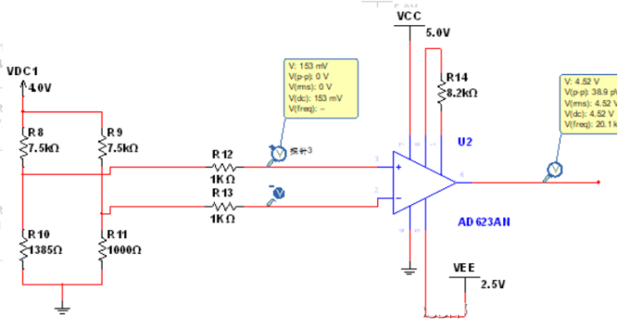
3. โซลูชันวงจรการเข้าซื้อกิจการ AD623
หลักการนี้สามารถอ้างอิงถึงหลักการวัดสะพานข้างต้นได้.
การได้มาที่อุณหภูมิต่ำ:
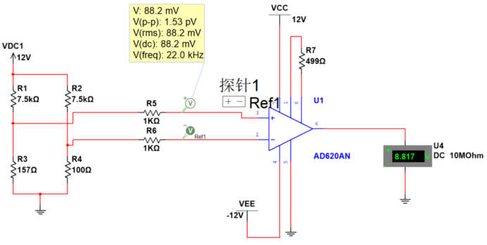
AD620 วัดค่าโซลูชันการเข้าซื้อกิจการ PT100 ที่อุณหภูมิสูง (150°)
การได้มาซึ่งอุณหภูมิสูง
ใส่คำอธิบายรูปภาพที่นี่
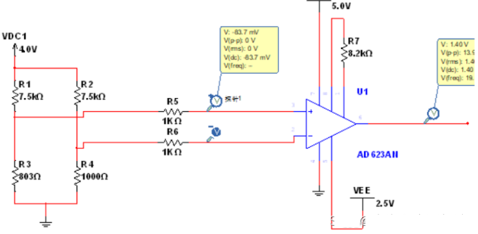
4. โซลูชันวงจรการเข้าซื้อกิจการ AD620
โซลูชันการเข้าซื้อกิจการ AD620 PT100 สำหรับอุณหภูมิสูง (150°):

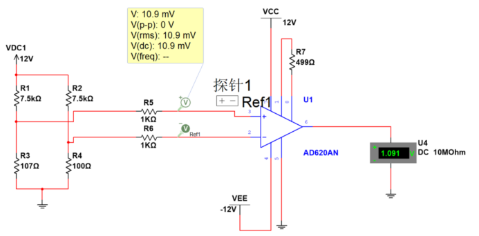
AD620 วัดโซลูชันการรับ PT100 ที่อุณหภูมิต่ำ (-40°)
โซลูชันการเข้าซื้อกิจการ AD620 PT100 สำหรับอุณหภูมิต่ำ (-40°):
AD620 วัดรูปแบบการรับ PT100 ที่อุณหภูมิห้อง (20°)
โซลูชันการเข้าซื้อกิจการ AD620 PT100 สำหรับอุณหภูมิห้อง (20°):
วงจรรับเซ็นเซอร์ PT100 อุณหภูมิสูง
5. การวิเคราะห์การกรองสัญญาณรบกวนของเซ็นเซอร์ PT100 และ PT1000
การได้มาซึ่งอุณหภูมิในบางส่วน, สภาพแวดล้อมที่รุนแรงหรือพิเศษจะได้รับการรบกวนที่ดีเยี่ยม, ส่วนใหญ่รวมถึง EMI และ REI. ตัวอย่างเช่น, ในการประยุกต์ใช้การได้มาของอุณหภูมิมอเตอร์, การรบกวนความถี่สูงที่เกิดจากการควบคุมมอเตอร์และการหมุนด้วยความเร็วสูงของมอเตอร์.
นอกจากนี้ยังมีสถานการณ์การควบคุมอุณหภูมิจำนวนมากภายในการบินและยานพาหนะการบินและอวกาศ, การวัดและควบคุมระบบพลังงานและระบบควบคุมสิ่งแวดล้อม. แกนกลางของการควบคุมอุณหภูมิคือการวัดอุณหภูมิ. เนื่องจากความต้านทานของเทอร์มิสเตอร์สามารถเปลี่ยนเป็นเส้นตรงตามอุณหภูมิ, การใช้ความต้านทานแพลตตินัมเพื่อวัดอุณหภูมิเป็นวิธีการวัดอุณหภูมิที่มีความแม่นยำสูงที่มีประสิทธิภาพ. ปัญหาหลักมีดังนี้:
1. มีการแนะนำความต้านทานบนลวดตะกั่วได้อย่างง่ายดาย, จึงส่งผลต่อความแม่นยำในการวัดของเซ็นเซอร์;
2. ในสภาพแวดล้อมการรบกวนทางแม่เหล็กไฟฟ้าที่รุนแรงบางอย่าง, สัญญาณรบกวนอาจถูกแปลงเป็นข้อผิดพลาดออฟเซ็ตเอาท์พุต DC หลังจากได้รับการแก้ไขโดยแอมพลิฟายเออร์เครื่องดนตรี, มีผลต่อความแม่นยำในการวัด.
5.1 วงจรการซื้อกิจการการบินและอวกาศ
อ้างถึงการออกแบบวงจรการได้มาของ PT1000 ในอากาศสำหรับการรบกวนต่อต้านอิเล็กทรอนิกส์ในการบินที่แน่นอน.
รูปแบบวงจรการรับ AD623 สำหรับเซ็นเซอร์ PT100
ตัวกรองถูกตั้งไว้ที่ปลายสุดของวงจรการได้มา. วงจรประมวลผลล่วงหน้าการได้มาของ PT1000 เหมาะสำหรับการประมวลผลล่วงหน้าที่ป้องกันสัญญาณรบกวนแม่เหล็กไฟฟ้าของอินเทอร์เฟซอุปกรณ์อิเล็กทรอนิกส์ในอากาศ; วงจรเฉพาะคือ:
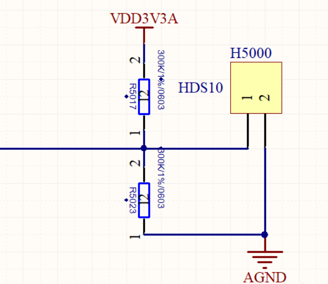
แรงดันไฟฟ้าอินพุต +15V จะถูกแปลงเป็นแหล่งแรงดันไฟฟ้าที่มีความแม่นยำสูง +5V ผ่านตัวควบคุมแรงดันไฟฟ้า. แหล่งจ่ายแรงดันไฟฟ้าความแม่นยำสูง +5V เชื่อมต่อโดยตรงกับตัวต้านทาน R1, และปลายอีกด้านหนึ่งของตัวต้านทาน R1 แบ่งออกเป็นสองเส้นทาง. หนึ่งเชื่อมต่อกับปลายอินพุตในเฟสของออปแอมป์, และอีกอันเชื่อมต่อกับปลายตัวต้านทาน PT1000 A ผ่านตัวกรองชนิด T S1. เอาต์พุตของออปแอมป์เชื่อมต่อกับอินพุทแบบกลับด้านเพื่อสร้างตัวติดตามแรงดันไฟฟ้า, และอินพุทอินพุทจะต่อเข้ากับพอร์ตกราวด์ของตัวควบคุมแรงดันไฟฟ้าเพื่อให้แน่ใจว่าแรงดันไฟฟ้าที่อินพุทอินเฟสจะเป็นศูนย์เสมอ. หลังจากผ่านตัวกรอง S2 แล้ว, ปลายด้านหนึ่งของตัวต้านทาน PT1000 แบ่งออกเป็นสองเส้นทาง, ตัวต้านทานหนึ่งตัวผ่าน R4 เป็นอินพุตแรงดันดิฟเฟอเรนเชียล D, และหนึ่งผ่านตัวต้านทาน R2 ถึง AGND. หลังจากผ่านตัวกรอง S3, ปลายอีกด้าน B ของตัวต้านทาน PT1000 แบ่งออกเป็นสองเส้นทาง, ตัวต้านทานหนึ่งตัวผ่าน R5 เป็นอินพุตแรงดันดิฟเฟอเรนเชียล E, และหนึ่งผ่านตัวต้านทาน R3 ถึง AGND. D และ E เชื่อมต่อผ่านตัวเก็บประจุ C3, D เชื่อมต่อกับ AGND ผ่านตัวเก็บประจุ C1, และ E เชื่อมต่อกับ AGND ผ่านตัวเก็บประจุ C2. ค่าความต้านทานที่แม่นยำของ PT1000 สามารถคำนวณได้โดยการวัดแรงดันดิฟเฟอเรนเชียลระหว่าง D และ E.
แรงดันไฟฟ้าอินพุต +15V จะถูกแปลงเป็นแหล่งแรงดันไฟฟ้าที่มีความแม่นยำสูง +5V ผ่านตัวควบคุมแรงดันไฟฟ้า. +5V เชื่อมต่อโดยตรงกับ R1. ปลายอีกด้านของ R1 แบ่งออกเป็นสองเส้นทาง, หนึ่งเชื่อมต่อกับอินพุตในเฟสของออปแอมป์, และอีกอันเชื่อมต่อกับปลาย A ของตัวต้านทาน PT1000 ผ่านตัวกรองชนิด T S1. เอาต์พุตของออปแอมป์เชื่อมต่อกับอินพุทแบบกลับด้านเพื่อสร้างตัวติดตามแรงดันไฟฟ้า, และอินพุตกลับด้านเชื่อมต่อกับพอร์ตพื้น. ในเวลานี้, กระแสที่ไหลผ่าน R1 เป็นค่าคงที่ 0.5mA. ตัวควบคุมแรงดันไฟฟ้าใช้ AD586TQ/883B, และแอมป์ OP ใช้ OP467A.
หลังจากผ่านตัวกรอง S2 แล้ว, ปลายด้านหนึ่งของตัวต้านทาน PT1000 แบ่งออกเป็นสองเส้นทาง, หนึ่งผ่านตัวต้านทาน R4 เป็นแรงดันไฟฟ้าที่แตกต่างกัน, และหนึ่งผ่านตัวต้านทาน R2 ถึง AGND. หลังจากผ่านตัวกรอง S3, ปลายอีกด้าน B ของตัวต้านทาน PT1000 แบ่งออกเป็นสองเส้นทาง, หนึ่งผ่านตัวต้านทาน R5 เป็นอินพุตแรงดันไฟฟ้าที่แตกต่างกัน, และหนึ่งผ่านตัวต้านทาน R3 ถึง AGND. D และ E เชื่อมต่อผ่านตัวเก็บประจุ C3, D เชื่อมต่อกับ AGND ผ่านตัวเก็บประจุ C1, และ E เชื่อมต่อกับ AGND ผ่านตัวเก็บประจุ C2.
ความต้านทานของ R4 และ R5 คือ 4.02k โอห์ม, ความต้านทานของ R1 และ R2 คือ 1m ohms, ความจุของ C1 และ C2 คือ 1,000pf, และความจุของ C3 คือ 0.047UF. R4, R5, C1, C2, และ C3 รวมกันเป็นเครือข่ายตัวกรอง RFI. ตัวกรอง RFI ทำการกรองสัญญาณอินพุตผ่านความถี่ต่ำให้เสร็จสิ้น, และวัตถุที่ถูกกรองออกนั้นรวมถึงการรบกวนแบบดิฟเฟอเรนเชียลและการรบกวนแบบโหมดร่วมที่มีในสัญญาณดิฟเฟอเรนเชียลอินพุต. การคำนวณความถี่ cutoff ‑3dB ของการรบกวนโหมดทั่วไปและการรบกวนโหมดที่แตกต่างกันในสัญญาณอินพุตจะแสดงในสูตร:
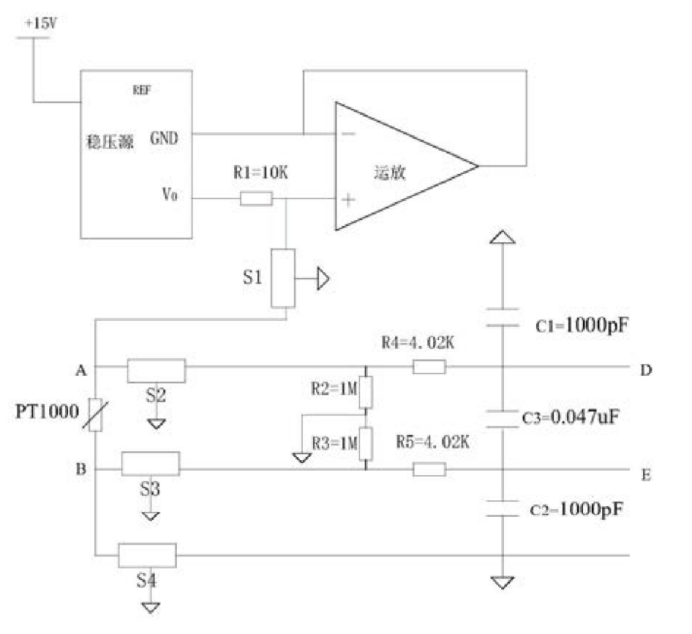
วงจรการซื้อกิจการการบินและอวกาศ
การแทนที่ค่าความต้านทานในการคำนวณ, ความถี่ในการตัดโหมดทั่วไปคือ 40kHz, และความถี่ในการตัดโหมดเชิงอนุพันธ์คือ 2.6kHz.
จุดสิ้นสุด B เชื่อมต่อกับ AGND ผ่านตัวกรอง S4. ในหมู่พวกเขา, เทอร์มินัลภาคพื้นดินของตัวกรองจาก S1 ถึง S4 นั้นเชื่อมต่อกับสนามป้องกันเครื่องบิน. เนื่องจากกระแสไหลผ่าน PT1000 เป็นที่รู้จัก 0.05ma, ค่าความต้านทานที่แม่นยำของ PT1000 สามารถคำนวณได้โดยการวัดแรงดันต่างที่ปลายทั้งสองด้านของ D และ E.
S1 ถึง S4 ใช้ตัวกรองชนิด T, รุ่น GTL2012X‑103T801, ด้วยความถี่คัตออฟ M±20%. วงจรนี้แนะนำตัวกรองความถี่ต่ำผ่านกับสายอินเทอร์เฟซภายนอก และดำเนินการกรอง RFI บนแรงดันไฟฟ้าส่วนต่าง. เป็นวงจรประมวลผลล่วงหน้าสำหรับ PT1000, ช่วยลดสัญญาณรบกวนทางแม่เหล็กไฟฟ้าและรังสี RFI ได้อย่างมีประสิทธิภาพ, ซึ่งช่วยเพิ่มความน่าเชื่อถือของค่าที่รวบรวมได้อย่างมาก. นอกจากนี้, แรงดันไฟฟ้าจะวัดโดยตรงจากปลายทั้งสองด้านของตัวต้านทาน PT1000, ขจัดข้อผิดพลาดที่เกิดจากความต้านทานของตะกั่วและปรับปรุงความแม่นยำของค่าความต้านทาน.
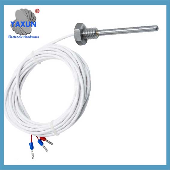 3-สายไฟ Class B สูงอุตสาหกรรมอุณหภูมิควบคุม PT100 Platinum เซ็นเซอร์อุณหภูมิตัวต้านทานความร้อน |
 เทอร์โมคัปเปิ้ลสปริงอัดชนิด K-E, โพรบเซ็นเซอร์อุณหภูมิ pt100 |
 เซ็นเซอร์อุณหภูมิ PT100 ความแม่นยำสูงสำหรับการวัดอุณหภูมิหม้อแปลงไฟฟ้า |
5.2 ตัวกรองชนิด T
ใส่คำอธิบายรูปภาพที่นี่
ตัวกรองชนิด T ประกอบด้วยตัวเหนี่ยวนำและตัวเก็บประจุสองตัว. ปลายทั้งสองด้านมีความต้านทานสูง, และประสิทธิภาพการสูญเสียการแทรกนั้นคล้ายกับของตัวกรองประเภทπ, แต่มันไม่ได้มีแนวโน้มที่จะ “ซึ่งส่งเสียงดัง” และสามารถใช้ในการสลับวงจร.