 English
 Afrikaans
 العربية
 বাংলা
বাংলা bosanski jezik
 Български
 Català
 粤语
粤语 中文(简体)
 中文(漢字)
 Hrvatski
 Čeština
 Nederlands
 Eesti keel
 Suomi
Suomi Français
 Deutsch
 Ελληνικά
 हिन्दी; हिंदी
 Magyar
 Bahasa Indonesia
 Italiano
 日本語
日本語 한국어
한국어 Latviešu valoda
 Lietuvių kalba
 македонски јазик
 Bahasa Melayu
 Norsk
Norsk پارسی
پارسی Polski
 Português
 Română
 Русский
 Cрпски језик
 Slovenčina
 Slovenščina
 Español
 Svenska
 ภาษาไทย
 Türkçe
 Українська
 اردو
اردو Tiếng Việt


A sonda e o cabo do sensor são a forma de embalagem do sensor, qual é a unidade mais básica do sensor. O sensor é embalado através de um circuito eletrônico razoável e estrutura de embalagem externa. Possui alguns componentes funcionais independentes que precisamos. Como o sensor, geralmente é dividido em: Sonda termistor NTC, Sonda PT100, Sonda PT1000, Sonda Ds18b20, sonda de temperatura da água, sonda de sensor automotivo, Sonda de RTDs, sonda de controle de temperatura, sonda de ajuste de temperatura, sonda de sensor de eletrodomésticos, etc..
|
Sonda sensor Ds18b20 com cabo |
Sonda de controle de temperatura com cabo |
Sonda sensor de temperatura PT100 com cabo |
Uma estrutura de sonda NTC baseada na previsão de temperatura e seu método de medição de temperatura, a sonda inclui: múltiplas sondas NTC; concha de cobre; estrutura metálica de suporte, fio e condutor de calor.
Etapa 1, entre m sondas NTC, obter as temperaturas T0, T1, …, Tn medido em intervalos de tempo iguais através de cada sonda NTC, onde n representa o número de série da temperatura coletada;
Etapa 2, calcular a diferença de temperatura vn=TnTn1 coletada em tempos de medição de temperatura adjacentes;
Etapa 3, calcule o parâmetro α=vn/vn1;
Etapa 4, calcular a temperatura prevista Tp=Tn1+vn/(1um) de uma única sonda;
Etapa 5, calcular a temperatura medida Tb. A presente invenção pode reduzir ainda mais o erro e tem boa aplicabilidade geral.
Análise completa de termistores!
🤔 Você sabe o que é um termistor? É um pouco especialista em circuitos eletrônicos!
👍 Termistores, em termos simples, são um tipo de elemento sensível que pode ajustar seu valor de resistência de acordo com as mudanças de temperatura.
🔥 Termistor de coeficiente de temperatura positivo (PTC), Quando a temperatura aumenta, seu valor de resistência aumentará significativamente. Este recurso faz brilhar em circuitos de controle automático!
|
Sonda sensor de temperatura da água com cabo |
Sensor NTC para forno de sonda para churrasco com cabo |
Sonda e cabo do sensor NTC |
❄️ O termistor de coeficiente de temperatura negativo (NTC) é o oposto, com a resistência diminuindo quando a temperatura aumenta. Em aparelhos domésticos, é frequentemente usado para partida suave, circuitos automáticos de detecção e controle.
💡 Agora você tem uma compreensão mais profunda dos termistores! No mundo eletrônico, é um papel indispensável!
1. Introdução ao NTC
O termistor NTC é um termistor com o nome da sigla de Coeficiente de Temperatura Negativo. Geralmente, O termo “termistor” refere-se a termistores NTC. Foi descoberto por Michael Faraday, que estava estudando semicondutores de sulfeto de prata na época, em 1833, e comercializado por Samuel Reuben na década de 1930. O termistor NTC é uma cerâmica semicondutora de óxido composta de manganês (Mn), níquel (Em) e cobalto (Co).
Pode ser visto em todos os lugares em nossas vidas. Devido à característica de que a resistência diminui com o aumento da temperatura, não é usado apenas como dispositivo sensor de temperatura em termômetros e condicionadores de ar, ou um dispositivo de controle de temperatura em smartphones, chaleiras e ferros, mas também usado para controle de corrente em equipamentos de fonte de alimentação. Recentemente, à medida que o grau de eletrificação dos veículos aumenta, termistores estão sendo cada vez mais usados em produtos automotivos.
2. Princípio de funcionamento
Geralmente, a resistência dos metais aumenta à medida que a temperatura aumenta. Isso ocorre porque o calor intensifica a vibração da rede, e a velocidade média de movimento dos elétrons livres diminui proporcionalmente.
Em contraste, a proporção de elétrons livres e lacunas em semicondutores aumenta devido à condução de calor, e esta parte é maior que a proporção da parte onde a velocidade diminui, então o valor da resistência diminui.
Além disso, devido à existência do band gap em semicondutores, quando aquecido externamente, elétrons na banda de valência passam para a banda de condução e conduzem eletricidade. Em outras palavras, o valor da resistência diminui à medida que a temperatura aumenta.
3. Características básicas
3.1 Características de resistência-temperatura (Características RT)
O valor da resistência de um termistor NTC é medido em uma corrente com autoaquecimento suficientemente baixo (calor gerado devido à corrente aplicada). Como padrão, é recomendado usar a corrente operacional máxima. E, o valor da resistência precisa ser expresso em pares com a temperatura.
A curva característica é descrita pela seguinte fórmula:
R0, R1: valor de resistência na temperatura T0, T1
T0, T1: temperatura absoluta
B: Constante B
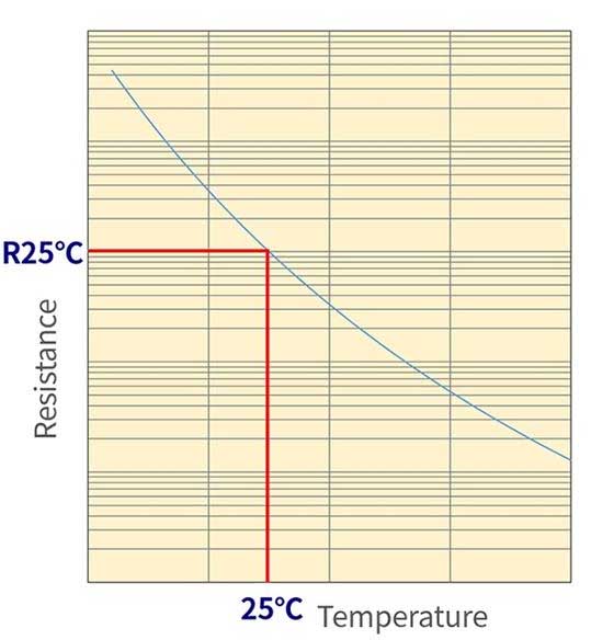
Características RT dos termistores NTC
Figura 1: Característica RT do termistor NTC
3.2 Constante B
A constante B é um valor único que caracteriza o termistor NTC. O ajuste da constante B sempre requer dois pontos. A constante B descreve a inclinação dos dois pontos.
Se os dois pontos forem diferentes, a constante B também será diferente, então preste atenção ao comparar. (Veja a figura 2)
O eixo horizontal é a característica de temperatura de 1-T
Figura 2: Diferentes constantes B selecionadas em 2 pontos
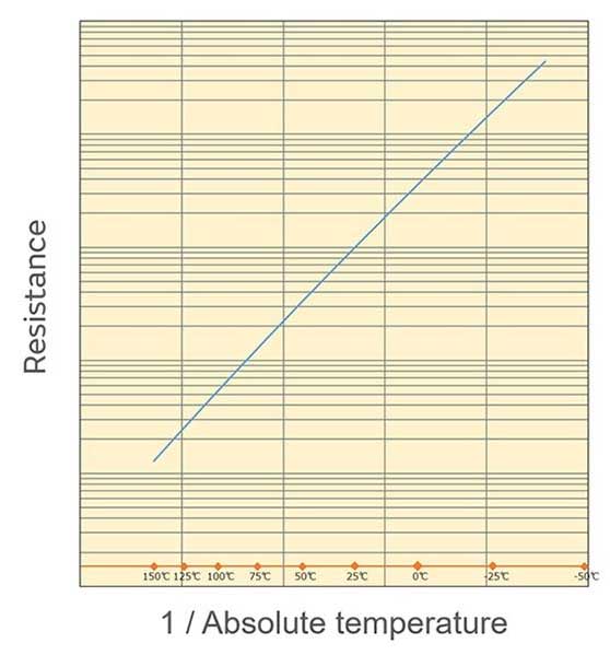
A partir disso, pode-se ver que B é a inclinação do lnR vs. 1/Curva T:
Murata usa 25°C e 50°C para definir a constante B, escrito como B (25/50).
Como mostrado na figura 3, 1/T (T é temperatura absoluta) está em proporção logarítmica com o valor da resistência. Percebe-se que a relação é próxima de uma linha reta.
Características VI dos termistores NTC
Figura 3: Características de temperatura com 1/T como eixo horizontal
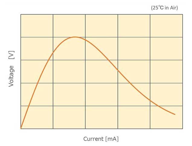
3.3 Características volt-ampere (V-I characteristics)
The V-I characteristics of NTC thermistors are shown in Figure 4.
Thermal dissipation constant per unit element
Figura 4: V-I characteristics of NTC thermistors
In the area with low current, the voltage of the ohmic contact gradually increases as the current gradually increases. The self-heating caused by the flow of current does not cause the temperature of the resistor to rise by dissipating heat from the surface of the thermistor and other parts.
No entanto, when the heat generation is large, the temperature of the thermistor itself rises and the resistance value decreases. In such an area, the proportional relationship between current and voltage no longer holds.
Geralmente, thermistors are used in an area where the self-heating is as low as possible. Como padrão, it is recommended that the operating current be kept below the maximum operating current.
If used in an area exceeding the voltage peak, thermal runaway reactions such as repeated heating and reduced resistance may occur, causing the thermistor to turn red or break. Please avoid using it in this range.
3.4 Coeficiente de temperatura de resistência (um)
The rate of change of the NTC thermistor per unit temperature is the temperature coefficient, which is calculated by the following formula.
Exemplo: When the temperature is close to 50°C and the B constant is 3380K
α = −3380/(273.15 + 50)² × 100 [%/°C] = −3.2 [%/°C]
Portanto, the temperature coefficient of resistance is as follows.
Thermal Time Constant of NTC Thermistor
α = − B/T² × 100 [%/°C]
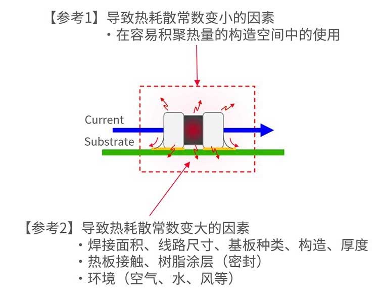
3.5 Thermal dissipation constant (δ)
When the ambient temperature is T1, when the thermistor consumes power P (hum) and its temperature changes to T2, the following formula holds.
P = δ (T2 − T1)
δ is the thermal dissipation constant (mW/°C). The above formula is transformed as follows.
NCU15 maximum voltage derating
δ = P/ (T2 − T1)
The thermal dissipation constant δ refers to the power required to increase the temperature by 1°C under self-heating conditions.
The thermal dissipation constant δ is determined by the balance between “self-heating due to power consumption” e “heat dissipation”, and therefore varies significantly depending on the thermistor’s operating environment.
Maximum operating current (Iop), maximum operating voltage (Vop)
Murata defined the concept of “thermal dissipation constant per unit element”.
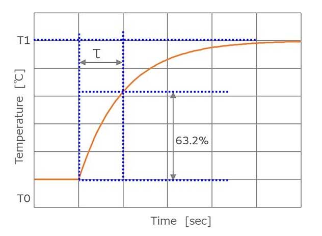
3.6 Constante de tempo térmico (t)
When a thermistor maintained at temperature T0 is suddenly changed to ambient temperature T1, the time it takes to change to the target temperature T1 is called the thermal time constant (t). Geralmente, this value refers to the time required to reach 63.2% of the temperature difference between T0 and T1.
Murata’s resistance value measurement method
When a thermistor maintained at one temperature (T0) is exposed to another temperature (T1), the temperature changes exponentially, and the temperature (T) after the elapse of time (t) is expressed as follows.
T = (T1 − T0) (1 − exp (−t/τ) ) + T0
Take t = τ,
T = (T1 − T0) (1−1/e) + T0
(T − T0)/(T1 − T0) = 1 − 1/e = 0.632
That is why τ is specified as the time to reach 63.2% of the temperature difference.
Figura 6: Thermal time constant of NTC thermistor
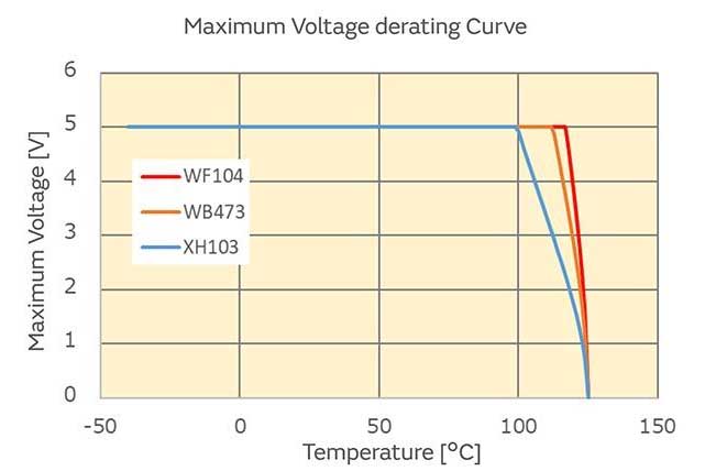
3.7 Tensão máxima (Vmax)
The maximum voltage that can be directly applied to the thermistor. When the applied voltage exceeds the maximum voltage, the product performance will deteriorate or even be destroyed.
Além disso, the temperature of the component rises due to self-heating. It is necessary to pay attention that the temperature of the component does not exceed the operating temperature range.
Output characteristics of resistor-grounded and thermistor-grounded circuits
Figura 7: Maximum voltage derating for NCU15 type
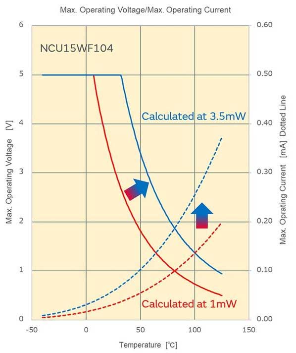
3.8 Maximum operating current (Iop), maximum operating voltage (Vop)
Murata defines the maximum operating current and maximum operating voltage as the current and voltage at which self-heating is 0.1℃ when applied. With reference to this value, thermistors can achieve more accurate temperature measurement.
Portanto, applying current/voltage exceeding the maximum operating current/voltage does not cause thermistor performance degradation. No entanto, please note that self-heating of the component will cause detection errors.
How Murata calculates the maximum operating current
When calculating the maximum operating current, the thermal dissipation constant (1mW/°C) defined by the unit component is required. The thermal dissipation constant indicates the degree of heat dissipation, but the heat dissipation state varies greatly depending on the working environment.
The working environment includes the material, grossura, estrutura, soldering area size, hot plate contact, resin packaging, etc.. of the substrate. The use of the unit component definition eliminates environmental interference factors.
De acordo com a experiência, the thermal dissipation constant in actual use is about 3 para 4 times that of the unit component. Assuming that the actual thermal dissipation constant is 3.5 vezes, the maximum operating current is shown in the blue curve in the figure. Compared with the case of 1mW/°C, it is now 1.9 vezes (√3.5 times).
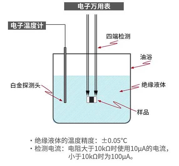
3.9 Zero load resistance value
The resistance value measured at a current (tensão) where self-heating is negligible. Como padrão, é recomendado usar a corrente operacional máxima.
Adjustment of R value and change of output characteristics
Figura 9: Murata’s resistance value measurement method
4. Como usar
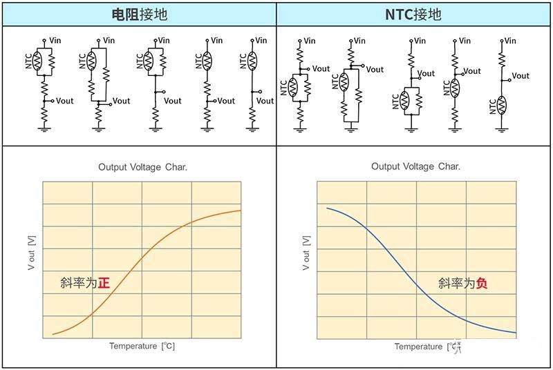
4.1 Diagrama de circuito
The output voltage may vary depending on the NTC thermistor wiring diagram. You can simulate it at the following URL on the Murata official website.
SimSurfing: NTC Thermistor Simulator (murata.co.jp)
Figura 10 Output characteristics of resistor grounding and thermistor grounding circuits
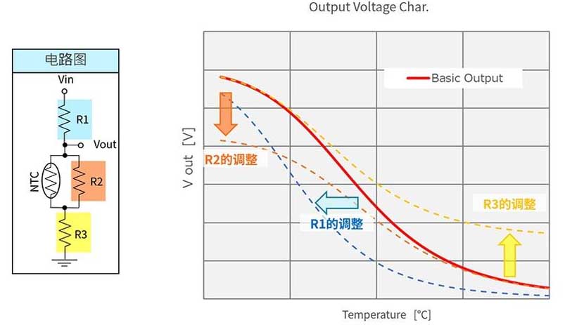
4.2 Adjustment of R1 (voltage divider resistor), R2 (parallel resistor), R3 (series resistor)
The output voltage may vary according to the circuit diagram.
Figura 11 Adjustment of R value and change of output characteristics
4.3 Calculation of detection error using Murata’s official tool
Select the relevant parameters of the NTC thermistor and the relevant parameters of the voltage divider circuit (reference voltage and voltage divider resistor, resistance accuracy), and then the error curve of temperature detection can be generated normally, as shown in the figure below:
Figura 12 Generating temperature detection error curve using official tools
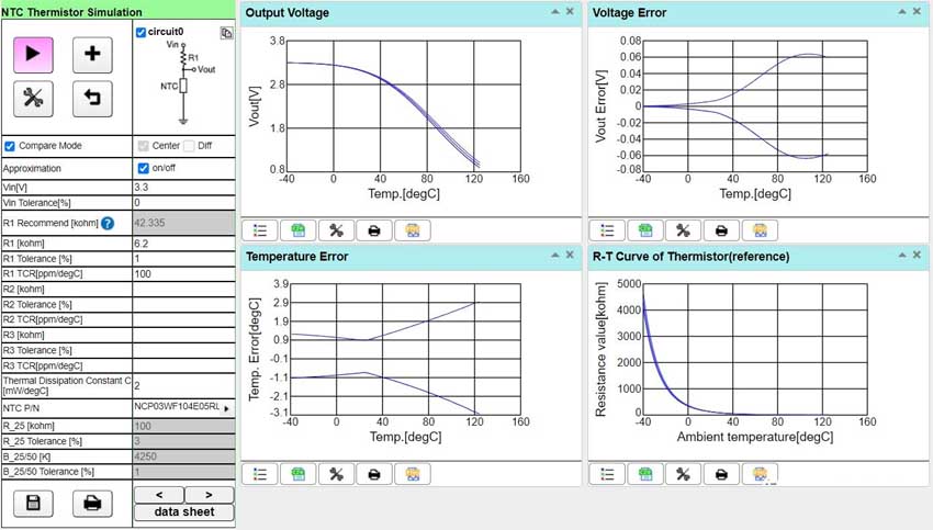
Tool generates temperature sensing NTC thermistor error curve