Productcategorieën
- thermische zekering 32
- opbouwzekeringen 12
- thermistor 36
- PCB-gemonteerde zekeringhouder 27
- Kabelboom 6
- Blade-zekeringhouders 17
- thermostaat 50
- Elektrische zekering 24
- Automotive temperatuursensor 7
- Thermische stroomonderbreker 22
- Zekeringkast-houder 36
- Temperatuursensor 75
- Thermische schakelaar 68
- Auto zekering 20
- Zekeringen vastschroeven 8
Producttags
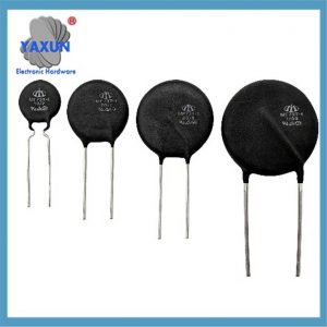
Toepassing en selectie van power thermistors
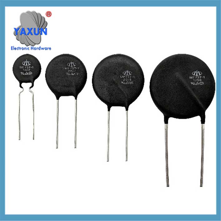
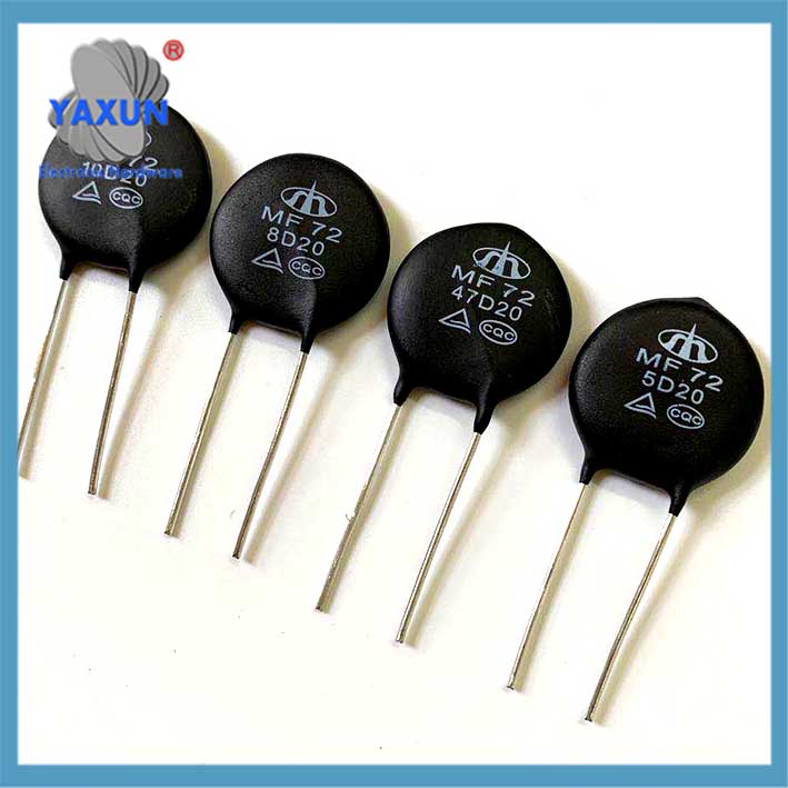
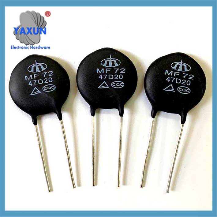
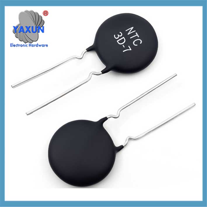
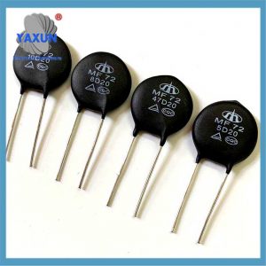
Wat is een power thermistor? Een power thermistor, Ook bekend als een Power NTC- of Inrush -huidige limiter, is een component die is ontworpen om druipende stromen in elektrische circuits te onderdrukken. Het maakt gebruik van het zelfverwarmende kenmerk van een negatieve temperatuurcoëfficiënt (NTC) thermistor om de hoge stromen te beperken die kunnen stijgen wanneer een circuit wordt ingeschakeld.
Vermogensthermistor (voornamelijk negatieve temperatuurcoëfficiënt NTC-type) is een sleutelcomponent voor het onderdrukken van stroomstoten in elektronische circuits. De belangrijkste parameters, selectiepunten en toepassingsscenario's zijn als volgt:
I. Kernfuncties en principes
Piekstroomonderdrukking
Op het moment dat de stroom wordt opgestart, de NTC-weerstandswaarde die in serie is geschakeld in het ingangscircuit is hoog, die de piekstroom kan beperken; nadat de stroom is ingeschakeld, de weerstand daalt snel als gevolg van hitte (Het stroomverbruik kan worden genegeerd), zorgen voor een stabiele werking van volgende circuits.
Negatieve temperatuurkenmerken
De weerstandswaarde neemt exponentieel af bij toenemende temperatuur: R(T)=R0⋅eB⋅(1T−1T0)R(T)=R0⋅eB⋅(T1−T01) (R0R0 is de weerstandswaarde bij 25℃, BB is de materiaalconstante).
Hoe het werkt:
Hoge initiële weerstand:
Wanneer de stroom voor het eerst wordt toegepast, een vermogensthermistor heeft een hoge weerstand, die de initiële inschakelstroom beperkt.
Zelfverwarmend:
Terwijl de stroom door de thermistor vloeit, het genereert warmte, waardoor de weerstand afneemt.
Weerstand afnemen:
Door de weerstandsvermindering kan het circuit de benodigde bedrijfsstroom trekken zonder de initiële piek.
Voordelen:
Beschermt apparatuur:
Door de inschakelstroom te beperken, vermogensthermostaten voorkomen schade aan gevoelige componenten en apparatuur.
Vermindert vermogensverlies:
De weerstandsafname door zelfverhitting vermindert het vermogensverlies vergeleken met het gebruik van een vaste weerstand.
Energiebesparing:
Het verminderen van het stroomverlies kan leiden tot energiebesparingen in toepassingen zoals schakelende voedingen en andere elektrische apparaten.
II. Belangrijkste parameters en selectiepunten
| Parameters | Definitie en selectiebelang | Typische waarde/bereik |
| Nominaal weerstandsvermogen van nul (R25) | De nominale weerstand bij 5°C bepaalt het initiële overspanningsonderdrukkingsvermogen. Berekeningsformule: R25≈U2⋅IsurgeR25≈2⋅IsurgeU (UU is de ingangsspanning, IsurgeIsurge is de stootstroom) | Veelgebruikte 2,5Ω, 5Oh, 10Ω±(15-30)% |
| Maximale stabiele stroom | De stroom die bij 25℃ lange tijd kan worden volgehouden, moet groter zijn dan de werkstroom van het circuit | Afhankelijk van het model 0,5A~tientallen ampère |
| Resterende weerstand | De minimale weerstandswaarde bij hoge temperaturen (zoals 100℃), die het normale stroomverbruik van het circuit beïnvloeden | Ongeveer 1/10~1/20 van R25 |
| B waarde | Materiaalconstante (gemeten bij 25℃~50℃), bepaalt de helling van de weerstandstemperatuurcurve; hoge B-waarde reageert snel, maar brengt hoge kosten met zich mee | 2000K~6000K |
| Thermische tijdconstante | Reactiesnelheidsindex, soort patch (zoals SMD) kan seconden bereiken | Glasafdichting/geëmailleerd draadtype ongeveer 10 ~ 60 seconden |
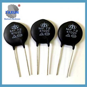
Opmerking: Voorbeeld van modelidentificatie MF72-10D-9:
10: R25=10Ω.
D: Schijfpakket
9: 9mm diameter;
III. Typische toepassingsscenario's
Voedingsapparatuur: Onderdrukking van ingangspieken van schakelende voeding, UPS, adapter;
Verlichtingssysteem: Anti-schokbescherming van LED-driver, ballast, verlichting verdeelkast;
Industriële apparatuur: Motorstart, industriële stroomvoorziening, medisch instrument;
HOUSEHOLD Appliances: Airconditioner, startbeveiliging voor koelkastcompressor;
Iv. Gids voor selectie en vermijding
Current matching
De maximale steady-state stroom moet groter zijn dan 1.5 keer de werkelijke werkstroom om continue verwarming en uitval te voorkomen.
Warmteafvoerontwerp
In scenario's met hoog vermogen, voldoende afstand of aanvullende warmteafvoer is vereist om te voorkomen dat overmatige temperatuurstijging onvoldoende restweerstand veroorzaakt.
Extreme temperatuur
Het bedrijfstemperatuurbereik is over het algemeen -55℃~+125℃. Modellen met glasverzegeling (bestand tegen 150℃) hebben de voorkeur in omgevingen met hoge temperaturen.
V. Pakket- en prestatievergelijking
| Pakkettype |
Voordelen | Toepasselijke scenario's |
| Epoxyhars | Lage kosten, goede waterdichtheid | Huishoudelijke apparaten, gewone voedingen |
| Glazen pakket | Bestand tegen hoge temperaturen (>150℃), snel antwoord | Industriële apparatuur, auto-elektronica |
| Type opbouwmontage (SMD) | Kleine maat, geschikt voor PCB's met hoge dichtheid | Compacte voedingsmodule |
Tip: Wees voorzichtig bij frequente overstapscenario's – NTC kan het vermogen tot piekonderdrukking verliezen als onvoldoende koeling onvoldoende is. Op dit moment, Er kan een parallelle relais-bypass worden aangesloten.
Neem contact met ons op
Wachten op uw e-mail, wij zullen u binnen antwoorden 12 uur met waardevolle informatie die u nodig had.
 English
 Afrikaans
 العربية
 বাংলা
বাংলা bosanski jezik
 Български
 Català
 粤语
粤语 中文(简体)
 中文(漢字)
 Hrvatski
 Čeština
 Nederlands
 Eesti keel
 Suomi
Suomi Français
 Deutsch
 Ελληνικά
 हिन्दी; हिंदी
 Magyar
 Bahasa Indonesia
 Italiano
 日本語
日本語 한국어
한국어 Latviešu valoda
 Lietuvių kalba
 македонски јазик
 Bahasa Melayu
 Norsk
Norsk پارسی
پارسی Polski
 Português
 Română
 Русский
 Cрпски језик
 Slovenčina
 Slovenščina
 Español
 Svenska
 ภาษาไทย
 Türkçe
 Українська
 اردو
اردو Tiếng Việt
