 English
 Afrikaans
 العربية
 বাংলা
বাংলা bosanski jezik
 Български
 Català
 粤语
粤语 中文(简体)
 中文(漢字)
 Hrvatski
 Čeština
 Nederlands
 Eesti keel
 Suomi
Suomi Français
 Deutsch
 Ελληνικά
 हिन्दी; हिंदी
 Magyar
 Bahasa Indonesia
 Italiano
 日本語
日本語 한국어
한국어 Latviešu valoda
 Lietuvių kalba
 македонски јазик
 Bahasa Melayu
 Norsk
Norsk پارسی
پارسی Polski
 Português
 Română
 Русский
 Cрпски језик
 Slovenčina
 Slovenščina
 Español
 Svenska
 ภาษาไทย
 Türkçe
 Українська
 اردو
اردو Tiếng Việt


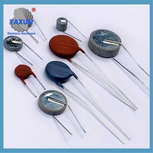
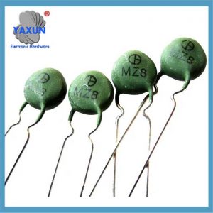
Overcurrent Protection PTC Thermistor
Termék áttekintése
Túláramvédelem A PTC termisztorok olyan védőelemek, amelyek automatikusan védenek a rendellenes hőmérsékletek és áramok ellen, és közismert nevén “visszaállítható biztosítékok” vagy “10,000-időbiztosítékok.” A hagyományos biztosítékokat helyettesítik, és széles körben használják a motorok túláram- és túlmelegedés elleni védelmére, transzformátorok, kapcsolóüzemű tápegységek, elektronikus áramkörök, és egyéb alkalmazások. Overcurrent protection PTC thermistors reduce residual current by limiting the power dissipation in the entire circuit through a sudden change in resistance. While traditional fuses cannot automatically reset after a circuit blows, overcurrent protection PTC thermistors return to their pre-protection state once the fault is removed. If a fault re-occurs, they can resume their overcurrent and overheat protection function.
When selecting an overcurrent protection PTC thermistor as an overcurrent and overheat protection component, first determine the maximum normal operating current of the circuit (the non-operating current of the PTC thermistor) and the maximum ambient temperature at the PTC thermistor’s installation location (during normal operation). Következő, consider the protection current (AZAZ., the tripping current of the overcurrent protection PTC thermistor), the maximum operating voltage, and the rated zero-power resistance. Factors such as the component’s dimensions should also be considered. The following figure shows the relationship between ambient operating temperature, non-tripping current, and tripping current.
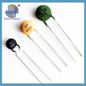 PTC termisztor túláramvédelemhez |
 PTC termisztor túláramvédelmi lemez 0R30 24V 1.8A 120C a Siemens helyett |
 1000V PTC Thermistor MZ8, 100 200R 75 fokok, 1KV, Túláram elleni védelem, Durable Ceramic |
Application Principle
When the circuit is operating normally, the current flowing through the overcurrent protection PTC thermistor is less than the rated current. The PTC thermistor maintains a low resistance and does not affect the normal operation of the protected circuit. When a circuit fault occurs and the current significantly exceeds the rated current, the PTC thermistor suddenly heats up, assuming a high-resistance state, placing the circuit in a relatively “off” state and thus protecting it from damage. Once the fault is resolved, the PTC thermistor automatically returns to a low-resistance state, and the circuit resumes normal operation.
Ábra 2 shows the volt-ampere characteristic curve and load curve for the circuit during normal operation. From point A to point B, the voltage applied to the PTC thermistor gradually increases, and the current flowing through it also increases linearly, indicating that the PTC thermistor’s resistance remains essentially unchanged, remaining in a low-resistance state. From point B to point E, the voltage gradually increases, and the PTC thermistor’s resistance rapidly increases due to heat generation. The current flowing through it also rapidly decreases, indicating that the PTC thermistor has entered its protection state. If the normal load curve is below point B, the PTC thermistor will not enter its protection state.
Általában, there are three types of overcurrent and overtemperature protection:
1. Current overcurrent (Ábra 3): RL1 is the load curve during normal operation. When the load resistance decreases, such as when a transformer line short circuits, the load curve changes from RL1 to RL2, exceeding point B, and the PTC thermistor enters its protection state.
2. Voltage overcurrent (Ábra 4): When the power supply voltage increases, such as when a 220V power line suddenly rises to 380V, the load curve changes from RL1 to RL2, exceeding point B, and the PTC thermistor enters its protection state.
3. Overheat (Ábra 5): When the ambient temperature rises above a certain limit, the PTC thermistor’s volt-ampere characteristic curve changes from A-B-E to A-B1-F. When the load curve RL exceeds point B1, the PTC thermistor enters protection mode.
Overcurrent Protection Circuit Diagram
| Modell | Rated Resistance R25(Ó) ±25% |
Non-operating Current Int(mA) |
Operating Current @25℃ It(mA) |
Maximum Operating Voltage Vmax(A) |
Maximum Current IMAX(A) |
Curie Temperature Tc(℃) |
Méretek (mm) | |||
| @25℃ | @60℃ | Dmax | Tmax | Фd | ||||||
| MZ11-20P3R7H265 | 3.7 | 530 | 430 | 1050 | 265 | 4.3 | 120(P) | 22.0 | 5.0 | 0.6 |
| MZ11-16P6R0H265 | 6.0 | 390 | 300 | 780 | 265 | 3.1 | 17.5 | 5.0 | 0.6 | |
| MZ11-16P7R0H265 | 7.0 | 350 | 280 | 700 | 265 | 3.1 | 17.5 | 5.0 | 0.6 | |
| MZ11-13P10RH265 | 10 | 260 | 200 | 520 | 265 | 1.8 | 14.0 | 5.0 | 0.6 | |
| MZ11-13P12RH265 | 12 | 225 | 180 | 450 | 265 | 1.8 | 14.0 | 5.0 | 0.6 | |
| MZ11-12P10RH265 | 10 | 250 | 200 | 500 | 265 | 1.8 | 13.5 | 5.0 | 0.6 | |
| MZ11-10P15RH265 | 15 | 180 | 140 | 350 | 265 | 1.2 | 11.0 | 5.0 | 0.6 | |
| MZ11-10P39RH265 | 39 | 130 | 100 | 250 | 265 | 1.2 | 11.0 | 5.0 | 0.6 | |
| MZ11-08P15RH265 | 15 | 150 | 120 | 300 | 265 | 0.8 | 9.0 | 5.0 | 0.6 | |
| MZ11-08P25RH265 | 25 | 130 | 100 | 250 | 265 | 0.8 | 9.0 | 5.0 | 0.6 | |
| MZ11-08P35RH265 | 35 | 115 | 90 | 225 | 265 | 0.8 | 9.0 | 5.0 | 0.6 | |
| MZ11-08P45RH265 | 45 | 105 | 80 | 220 | 265 | 0.8 | 9.0 | 5.0 | 0.6 | |
| MZ11-08P55RH265 | 55 | 90 | 70 | 180 | 265 | 0.8 | 9.0 | 5.0 | 0.6 | |
| MZ11-07P82RH265 | 82 | 70 | 50 | 140 | 265 | 0.6 | 8.0 | 5.0 | 0.6 | |
| MZ11-07P56RH265 | 56 | 90 | 60 | 175 | 265 | 0.6 | 8.0 | 5.0 | 0.6 | |
| MZ11-06P33RH265 | 33 | 110 | 85 | 220 | 265 | 0.4 | 7.0 | 5.0 | 0.6 | |
| MZ11-05P70RH265 | 70 | 65 | 50 | 130 | 265 | 0.3 | 6.5 | 5.0 | 0.6 | |
| MZ11-05P85RH265 | 85 | 60 | 45 | 120 | 265 | 0.3 | 6.5 | 5.0 | 0.6 | |
| MZ11-05P39RH265 | 39 | 80 | 65 | 160 | 265 | 0.2 | 6.5 | 5.0 | 0.6 | |
| MZ11-05P121H265 | 120 | 45 | 35 | 90 | 265 | 0.3 | 6.5 | 5.0 | 0.6 | |
| MZ11-05P181H265 | 180 | 40 | 30 | 80 | 265 | 0.3 | 6.5 | 5.0 | 0.6 | |
| MZ11-04P70RH265 | 70 | 50 | 40 | 100 | 265 | 0.2 | 5.5 | 5.0 | 0.6 | |
| MZ11-04P121H265 | 120 | 40 | 30 | 80 | 265 | 0.2 | 5.5 | 5.0 | 0.6 | |
| MZ11-03P151H265 | 150 | 40 | 30 | 75 | 265 | 0.2 | 4.5 | 5.0 | 0.5 | |
| MZ11-10N12RH265 | 12 | 170 | 130 | 340 | 265 | 1.2 | 100(N) | 11.0 | 5.0 | 0.6 |
| MZ11-10N18RH265 | 18 | 145 | 110 | 290 | 265 | 1.2 | 11.0 | 5.0 | 0.6 | |
| MZ11-10N22RH265 | 22 | 125 | 90 | 250 | 265 | 1.2 | 11.0 | 5.0 | 0.6 | |
| MZ11-07N22RH265 | 22 | 120 | 90 | 225 | 265 | 0.5 | 8.0 | 5.0 | 0.6 | |
| MZ11-05N151H265 | 150 | 38 | 30 | 80 | 265 | 0.3 | 6.5 | 5.0 | 0.6 | |
| MZ11-05N301H265 | 300 | 27 | 20 | 55 | 265 | 0.3 | 6.5 | 5.0 | 0.6 | |
| MZ11-05N601H265 | 600 | 20 | 15 | 40 | 265 | 0.2 | 6.5 | 5.0 | 0.6 | |
| MZ11-05N102H265 | 1000 | 15 | 12 | 30 | 265 | 0.2 | 6.5 | 5.0 | 0.6 | |
| MZ11-04N151H265 | 150 | 36 | 28 | 80 | 265 | 0.3 | 5.5 | 5.0 | 0.6 | |
| MZ11-03N151H265 | 150 | 33 | 25 | 65 | 265 | 0.2 | 4.5 | 5.0 | 0.5 | |
| MZ11-03N101H265 | 100 | 40 | 30 | 80 | 265 | 0.2 | 4.5 | 5.0 | 0.5 | |
| MZ11-03N70RH265 | 70 | 45 | 35 | 90 | 265 | 0.1 | 4.5 | 5.0 | 0.5 | |
| MZ11-08M12RH265 | 12 | 120 | 70 | 220 | 265 | 0.8 | 80(M) | 9.0 | 5.0 | 0.6 |
| MZ11-08M25RH265 | 25 | 85 | 50 | 170 | 265 | 0.8 | 9.0 | 5.0 | 0.6 | |
| MZ11-08M35RH265 | 35 | 80 | 50 | 150 | 265 | 0.8 | 9.0 | 5.0 | 0.6 | |
| MZ11-08M50RH265 | 50 | 60 | 40 | 120 | 265 | 1.0 | 9.0 | 5.0 | 0.6 | |
| MZ11-07M101H265 | 100 | 50 | 30 | 100 | 265 | 0.6 | 8.0 | 5.0 | 0.6 | |
| MZ11-05M70RH265 | 70 | 50 | 30 | 100 | 265 | 0.3 | 6.5 | 5.0 | 0.6 | |
| MZ11-05M121H265 | 120 | 30 | 20 | 60 | 265 | 0.3 | 6.5 | 5.0 | 0.6 | |
| MZ11-03M101H265 | 100 | 25 | 18 | 55 | 265 | 0.2 | 4.5 | 5.0 | 0.5 | |
| MZ11-03M151H265 | 150 | 22 | 15 | 45 | 265 | 0.2 | 4.5 | 5.0 | 0.5 | |
| Modell | Rated Resistance R25(Ó) ±25% |
Non-operating Current Int(mA) |
Operating Current @25℃ It(mA) |
Maximum Operating Voltage Vmax(A) |
Maximum Current IMAX(A) |
Curie Temperature Tc(℃) |
Méretek (mm) | |||
| @25℃ | @60℃ | Dmax | Tmax | Фd | ||||||
| MZ12-20P2R6H140 | 2.6 | 650 | 500 | 1300 | 140 | 4.3 | 120(P) | 22.0 | 5.0 | 0.6 |
| MZ12-16P4R7H140 | 4.7 | 425 | 330 | 850 | 140 | 3.1 | 17.5 | 5.0 | 0.6 | |
| MZ12-16P5R6H140 | 5.6 | 400 | 310 | 800 | 140 | 3.1 | 17.5 | 5.0 | 0.6 | |
| MZ12-13P6R8H140 | 6.8 | 325 | 250 | 650 | 140 | 1.8 | 14.0 | 5.0 | 0.6 | |
| MZ12-12P5R6H140 | 5.6 | 325 | 250 | 650 | 140 | 1.8 | 13.5 | 5.0 | 0.6 | |
| MZ12-12P6R8H140 | 6.8 | 300 | 230 | 600 | 140 | 1.8 | 13.5 | 5.0 | 0.6 | |
| MZ12-10P10RH140 | 10 | 225 | 170 | 450 | 140 | 1.2 | 11.0 | 5.0 | 0.6 | |
| MZ12-10P6R8H140 | 6.8 | 275 | 200 | 550 | 140 | 1.2 | 11.0 | 5.0 | 0.6 | |
| MZ12-08P22RH140 | 22 | 135 | 110 | 270 | 140 | 0.8 | 9.0 | 5.0 | 0.6 | |
| MZ12-06P25RH140 | 25 | 125 | 90 | 250 | 140 | 0.5 | 7.0 | 5.0 | 0.6 | |
| MZ12-05P33RH140 | 33 | 90 | 70 | 175 | 140 | 0.3 | 6.5 | 5.0 | 0.6 | |
| MZ12-16R2R1H140 | 2.1 | 710 | 570 | 1420 | 140 | 3.1 | 140(R) | 17.5 | 5.0 | 0.6 |
| MZ12-13R3R8H140 | 3.8 | 500 | 400 | 1000 | 140 | 1.8 | 14.0 | 5.0 | 0.6 | |
| MZ12-10R15RH140 | 15 | 210 | 170 | 420 | 140 | 1.2 | 11.0 | 5.0 | 0.6 | |
| MZ12-10R6R7H140 | 6.7 | 300 | 230 | 600 | 140 | 1.2 | 11.0 | 5.0 | 0.6 | |
| MZ12-10R10RH140 | 10 | 250 | 200 | 500 | 140 | 1.2 | 11.0 | 5.0 | 0.6 | |
| Modell | Rated Resistance R25(Ó) ±25% |
Non-operating Current Int(mA) |
Operating Current @25℃ It(mA) |
Maximum Operating Voltage Vmax(A) |
Maximum Current IMAX(A) |
Curie Temperature Tc(℃) |
Méretek (mm) | |||
| @25℃ | @60℃ | Dmax | Tmax | Фd | ||||||
| MZ13-10R1R8H30 | 1.8 | 650 | 550 | 1300 | 30 | 4.3 | 140(R) | 11.0 | 4.0 | 0.6 |
| MZ13-08R1R8H30 | 1.8 | 600 | 500 | 1100 | 30 | 3.0 | 9.0 | 4.0 | 0.6 | |
| MZ13-12P1R2H30 | 1.2 | 750 | 600 | 1500 | 30 | 5.5 | 120(P) | 13.5 | 4.0 | 0.6 |
| MZ13-12P1R8H30 | 1.8 | 500 | 430 | 1000 | 30 | 5.5 | 13.5 | 4.0 | 0.6 | |
| MZ13-10P2R7H30 | 2.7 | 380 | 320 | 700 | 30 | 4.3 | 11.0 | 4.0 | 0.6 | |
| MZ13-08P1R8H30 | 1.8 | 550 | 450 | 1000 | 30 | 3.0 | 9.0 | 4.0 | 0.6 | |
| MZ13-08P4R2H30 | 4.2 | 280 | 230 | 560 | 30 | 3.0 | 9.0 | 4.0 | 0.6 | |
| MZ13-05P10RH30 | 10 | 170 | 140 | 340 | 30 | 1.0 | 6.5 | 4.0 | 0.6 | |
| MZ14-16P2R3H60 | 2.3 | 550 | 450 | 1100 | 60 | 8.0 | 17.5 | 4.0 | 0.6 | |
| MZ14-12P3R7H60 | 3.7 | 380 | 320 | 750 | 60 | 5.5 | 13.5 | 4.0 | 0.6 | |
| MZ14-10P5R6H60 | 5.6 | 300 | 250 | 600 | 60 | 4.3 | 11.0 | 4.0 | 0.6 | |
| MZ14-08P9R4H60 | 9.4 | 180 | 150 | 360 | 60 | 3.0 | 9.0 | 4.0 | 0.6 | |
| MZ14-05P25RH60 | 25 | 100 | 85 | 200 | 60 | 1.0 | 6.5 | 4.0 | 0.6 | |
| MZ14-03P55RH60 | 55 | 60 | 50 | 120 | 60 | 0.7 | 4.5 | 4.0 | 0.5 | |
| MZ14-08M4R7H60 | 4.7 | 180 | 120 | 360 | 60 | 3.0 | 80(M) | 9.0 | 4.0 | 0.6 |
| Modell | Rated Resistance R25(Ó) ±25% |
Non-operating Current Int(mA) |
Operating Current @25℃ It(mA) |
Maximum Operating Voltage Vmax(A) |
Maximum Current IMAX(A) |
Curie Temperature Tc(℃) |
Méretek (mm) | |||
| @25℃ | @60℃ | Dmax | Tmax | Фd | ||||||
| MZ15-10R1R2H15 | 1.2 | 850 | 700 | 1550 | 15 | 4.3 | 140(R) | 11.0 | 4.0 | 0.6 |
| MZ15-08R1R0H15 | 1.0 | 850 | 700 | 1500 | 15 | 3.0 | 9.0 | 4.0 | 0.6 | |
| MZ15-08R1R8H15 | 1.8 | 600 | 500 | 1100 | 15 | 3.0 | 9.0 | 4.0 | 0.6 | |
| MZ15-07R1R0H15 | 1.0 | 750 | 600 | 1350 | 15 | 2.5 | 8.0 | 4.0 | 0.6 | |
| MZ15-07R1R2H15 | 1.2 | 650 | 550 | 1200 | 15 | 2.5 | 8.0 | 4.0 | 0.6 | |
| MZ15-05R4R6H15 | 4.6 | 350 | 300 | 680 | 15 | 1.0 | 6.5 | 4.0 | 0.6 | |
| MZ15-03R13RH15 | 13 | 180 | 150 | 350 | 15 | 0.7 | 4.5 | 4.0 | 0.5 | |
| MZ15-10P1R2H18 | 1.2 | 700 | 600 | 1400 | 18 | 4.3 | 120(P) | 11.0 | 4.0 | 0.6 |
| MZ15-08P1R0H18 | 1.0 | 650 | 550 | 1200 | 18 | 3.0 | 9.0 | 4.0 | 0.6 | |
| MZ15-08P1R8H18 | 1.8 | 550 | 450 | 1000 | 18 | 3.0 | 9.0 | 4.0 | 0.6 | |
| MZ15-05P4R6H18 | 4.6 | 300 | 250 | 580 | 18 | 1.0 | 6.5 | 4.0 | 0.6 | |
| MZ15-03P13RH18 | 13 | 145 | 120 | 280 | 18 | 0.7 | ||||
Modell paraméterei
General-Purpose PTC Thermistor for Overcurrent Protection
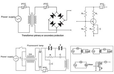
PTC overcurrent protection circuit diagram
Selection Guide for PTC Thermistors for Overcurrent Protection
Model parameters of PTC overcurrent protection thermistor
1. Maximum Operating Voltage
When a PTC thermistor is connected in series in a circuit, only a small portion of the voltage remains across it during normal operation. When the PTC thermistor activates and assumes a high-resistance state, it must withstand nearly the entire power supply voltage. Ezért, when selecting a PTC thermistor, ensure that it has a sufficiently high maximum operating voltage, while also taking into account potential power supply voltage fluctuations.
2. Non-operating Current and Operate Current
To ensure reliable switching, the operate current must be at least twice the non-operating current.
Because ambient temperature significantly affects both the non-operating and operate currents (see the figure below), worst-case scenarios must be considered. The non-operating current should be selected at the maximum allowable ambient temperature, while the operate current should be selected at a lower ambient temperature.
3. Maximum Allowable Current at Maximum Operating Voltage
When a PTC thermistor is required to perform a protective function, check the circuit for conditions that could generate currents exceeding the maximum allowable value. This generally refers to situations where there is a risk of a short circuit. The data sheet specifies the maximum current value. Exceeding this value may damage or prematurely fail the PTC thermistor.
4. Kapcsolási hőmérséklet (Curie Temperature)
We offer overcurrent protection components with Curie temperatures of 80°C, 100°C, 120°C, and 140°C. The non-operating current depends on the Curie temperature and the diameter of the PTC thermistor chip. To reduce costs, components with high Curie temperatures and small dimensions should be selected. Továbbá, consideration should be given to whether such a PTC thermistor’s high surface temperature may cause undesirable side effects in the circuit. Általában, the Curie temperature should exceed the maximum ambient operating temperature by 20 to 40°C.
5. Environmental Impact
When exposed to chemicals or when using potting compounds or fillers, extreme caution must be exercised. This can reduce the effectiveness of the PTC thermistor due to reduction of the barium titanate ceramic. Changes in thermal conductivity caused by potting can also lead to localized overheating and damage.
Függelék: Example of Selecting a PTC Thermistor for Power Transformer Overcurrent Protection
A power transformer has a primary voltage of 220V, a secondary voltage of 16V, and a secondary current of 1.5A. During a secondary overcurrent condition, the primary current is approximately 350mA, and protection should be activated within 10 jegyzőkönyv. The transformer’s operating temperature ranges from -10°C to 40°C, with a temperature rise of 15°C to 20°C during normal operation. The PTC thermistor is installed close to the transformer. Please select a PTC thermistor for primary protection.
1. Determine the Maximum Operating Voltage
The transformer’s operating voltage is 220V. Considering power supply fluctuations, the maximum operating voltage should be 220V x (1 + 20%) = 264V.
The maximum operating voltage of the PTC thermistor is 265V.
2. Determine the Non-operating Current
Calculations and measurements show that the primary current of the transformer is 125mA during normal operation. Considering that the ambient temperature at the PTC thermistor’s installation location can reach up to 60°C, the non-operating current at 60°C should be 130-140mA.
3. Determining the Operate Current
Considering that the ambient temperature at the PTC thermistor’s installation location can reach as low as -10°C or 25°C, the operating current should be 340-350mA at -10°C or 25°C, with an operating time of approximately 5 jegyzőkönyv.
4. Determining the Rated Zero-Power Resistor R25
When a PTC thermistor is connected in series with the primary, the voltage drop generated should be minimized. The PTC thermistor’s own heat generation should also be minimized. Általában, the voltage drop of a PTC thermistor should be less than 1% of the total power supply. R25 is calculated as follows:
220V × 1% ÷ 0.125A = 17.6Ω
5. Determining the Maximum Current
According to actual measurements, when the transformer’s secondary is short-circuited, the primary current can reach 500mA. Considering the increased current flowing through the primary coil when a partial short circuit occurs, the maximum current of the PTC thermistor should be above 1A.
6. Determine the Curie Temperature and Dimensions
Considering that the ambient temperature at the PTC thermistor’s installation location can reach up to 60°C, add 40°C to this value when selecting the Curie temperature, resulting in a Curie temperature of 100°C. Viszont, considering cost and the fact that the PTC thermistor is not installed within the transformer winding, its higher surface temperature will not adversely affect the transformer, so a Curie temperature of 120°C can be selected. This allows the PTC thermistor’s diameter to be reduced, reducing costs.
7. Determine the PTC thermistor Model
Based on the above requirements, after consulting our company’s specifications sheet, we selected the MZ11-10P15RH265. Azaz: maximum operating voltage 265V, rated zero-power resistance 15Ω ± 25%, non-operating current 140 mA, operating current 350 mA, maximum current 1.2A, Curie temperature 120°C, and maximum size ø11.0mm.
PTC Failure Modes
There are two main indicators for measuring the reliability of PTC thermistors:
A. Voltage Withstand Capacity: Exceeding the specified voltage can cause a PTC thermistor to short-circuit and break down. Applying a high voltage eliminates products with low voltage withstand capacity, ensuring that PTC thermistors are safe below the maximum operating voltage (Vmax).
B. Current Withstand Capacity: Exceeding the specified current or number of switching cycles can cause a PTC thermistor to exhibit an irreversible high-resistance state and fail. Cyclic on-off testing cannot completely eliminate premature failures.
Under specified operating conditions, a PTC thermistor exhibits a high-resistance state after failure. Long-term voltage application to a PTC thermistor (generally greater than 1000 óra) results in a minimal increase in its resistance at room temperature. This increase is more pronounced in PTC heating elements with a Curie temperature exceeding 200°C. Besides PTC heating elements, the primary cause of PTC failure is stress cracking in the center of the ceramic during switching. During the operation of a PTC thermistor, uneven distributions of temperature, resistivity, electric field, and power density within the PTC ceramic lead to high stress at the center, resulting in delamination and cracking.