catégories de produits
- fusion thermique 32
- fusibles à montage en surface 12
- thermistance 36
- Porte-fusible à montage sur circuit imprimé 27
- Faisceau de câblage 6
- Porte-fusibles à lame 17
- thermostat 50
- Fusible électrique 24
- Capteur de température automobile 7
- Disjoncteur thermique 22
- Porte-boîte à fusibles 36
- Capteur de température 75
- Interrupteur thermique 68
- Fusible de voiture 20
- Fusibles boulonnés 8
Mots clés du produit
Application et sélection des thermistances de puissance
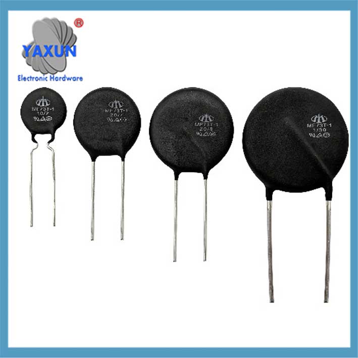
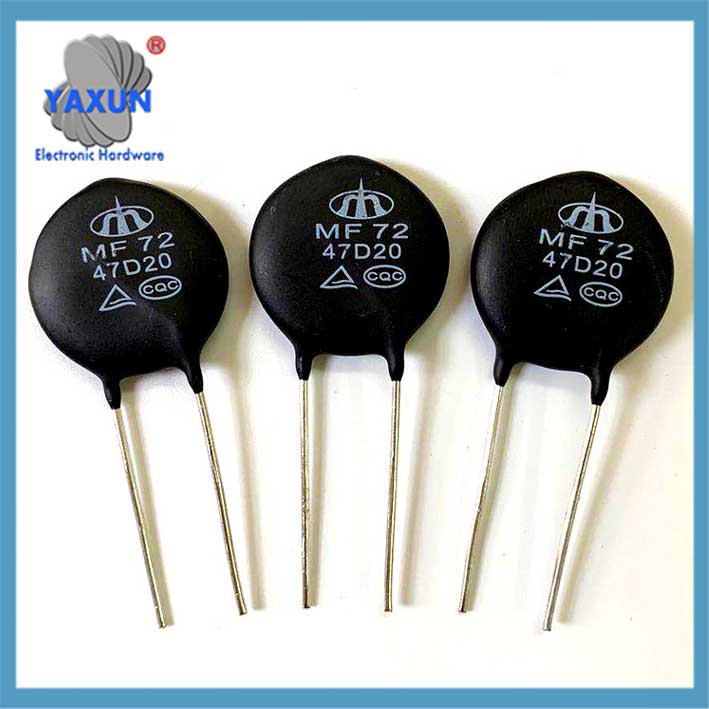
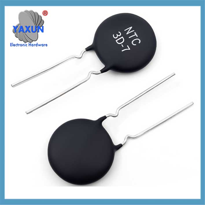
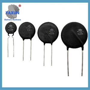
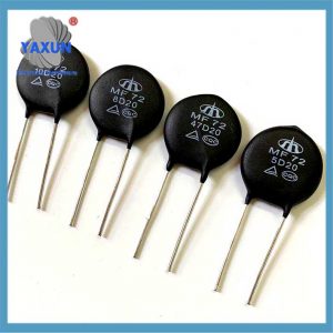
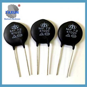
Qu'est-ce qu'une thermistance de puissance? Une thermistance de puissance, également connu sous le nom de NTC de puissance ou limiteur de courant d'appel, est un composant conçu pour supprimer les courants d'appel dans les circuits électriques. Il utilise la caractéristique d'auto-échauffement d'un coefficient de température négatif (CTN) thermistance pour limiter les courants élevés qui peuvent surgir lorsqu'un circuit est allumé.
Thermistance de puissance (coefficient de température principalement négatif type NTC) est un composant clé pour supprimer les surintensités dans les circuits électroniques. Ses principaux paramètres, les points de sélection et les scénarios d'application sont les suivants:
je. Fonctions et principes de base
Suppression des surintensités
Au moment de la mise sous tension, la valeur de résistance NTC connectée en série dans le circuit d'entrée est élevée, ce qui peut limiter le courant de pointe; après la mise sous tension, la résistance chute rapidement à cause de la chaleur (la consommation d'énergie peut être ignorée), assurer le fonctionnement stable des circuits suivants.
Caractéristiques de température négatives
La valeur de la résistance diminue de façon exponentielle avec l'augmentation de la température: R.(T)=R0⋅eB⋅(1T−1T0)R.(T)=R0⋅eB⋅(T1−T01) (R0R0 est la valeur de résistance à 25℃, BB est la constante matérielle).
Comment ça marche:
Résistance initiale élevée:
Lors de la première mise sous tension, une thermistance de puissance a une résistance élevée, ce qui limite le courant d'appel initial.
Auto-chauffant:
Lorsque le courant traverse la thermistance, ça génère de la chaleur, provoquant une diminution de sa résistance.
Diminution de la résistance:
La réduction de la résistance permet au circuit de consommer le courant de fonctionnement nécessaire sans la surtension initiale.
Avantages:
Protège l'équipement:
En limitant le courant d'appel, les thermostats de puissance évitent d'endommager les composants et équipements sensibles.
Réduit la perte de puissance:
La diminution de la résistance grâce à l'auto-échauffement réduit la perte de puissance par rapport à l'utilisation d'une résistance fixe.
Économies d'énergie:
La réduction des pertes de puissance peut conduire à des économies d'énergie dans des applications telles que les alimentations à découpage et autres appareils électriques..
II. Paramètres clés et points de sélection
| Paramètres | Définition et signification de la sélection | Valeur/plage typique |
| Résistance nominale à puissance nulle (R25) | La résistance nominale à 5°C détermine la capacité initiale de suppression des surtensions. Formule de calcul: R25≈U2⋅IsurgeR25≈2⋅IsurgeU (UU est la tension d'entrée, IsurgeIsurge est le courant de surtension) | Couramment utilisé 2,5Ω, 5Oh, 10Ω ±(15-30)% |
| Courant maximal en régime permanent | Le courant qui peut être soutenu longtemps à 25 ℃, doit être supérieur au courant de fonctionnement du circuit | Selon le modèle 0,5A ~ dizaines d'ampères |
| Résistance résiduelle | La valeur minimale de résistance à haute température (comme 100 ℃), affectant la consommation électrique normale du circuit | Environ 1/10~1/20 de R25 |
| Valeur b | Constante matérielle (mesuré à 25℃~50℃), détermine la pente de la courbe résistance-température; une valeur B élevée répond rapidement mais a un coût élevé | 2000K~6000K |
| Constante de temps thermique | Indice de vitesse de réponse, type de patch (comme CMS) peut atteindre quelques secondes | Joint en verre/type de fil émaillé environ 10 à 60 secondes |
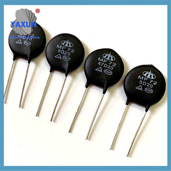
Note: Exemple d'identification du modèle MF72-10D-9:
10: R25=10Ω.
D: Paquet de disques
9: 9mm diamètre;
III. Scénarios d'application typiques
Équipement d'alimentation électrique: Suppression des surtensions d'entrée de l'alimentation à découpage, UPS, adaptateur;
Système d'éclairage: Protection antichoc du driver LED, ballast, boîte de distribution d'éclairage;
Équipement industriel: Démarrage du moteur, alimentation industrielle, instrument médical;
Appareils de maison: Climatiseur, protection contre le démarrage du compresseur du réfrigérateur;
Iv. Guide de sélection et d’évitement
correspondance actuelle
Le courant maximum en régime permanent doit être supérieur à 1.5 fois le courant de fonctionnement réel pour éviter un chauffage et une panne continus.
Conception de dissipation thermique
Dans des scénarios à haute puissance, un espacement suffisant ou une dissipation thermique auxiliaire est nécessaire pour éviter qu'une élévation excessive de la température ne provoque une résistance résiduelle insuffisante.
Température extrême
La plage de température de fonctionnement est généralement de -55℃~+125℃. Modèles vitrés (résistant à 150 ℃) sont préférés dans les environnements à haute température.
V. Comparaison des packages et des performances
| Type de colis |
Avantages | Scénarios applicables |
| Résine époxy | Faible coût, bonne imperméabilité | Appareils électroménagers, alimentations ordinaires |
| Paquet de verre | Résistance à haute température (>150℃), réponse rapide | Équipement industriel, électronique automobile |
| Type de montage en surface (SMD) | Petite taille, adapté aux PCB haute densité | Module d'alimentation compact |
Conseil: Soyez prudent dans les scénarios de changement fréquents – NTC peut perdre sa capacité de suppression des surtensions lorsqu'un refroidissement insuffisant est insuffisant. A cette époque, un bypass de relais parallèle peut être connecté.
Contactez-nous
En attente de votre email, nous vous répondrons dans les 12 heures avec des informations précieuses dont vous aviez besoin.
 English
 Afrikaans
 العربية
 বাংলা
বাংলা bosanski jezik
 Български
 Català
 粤语
粤语 中文(简体)
 中文(漢字)
 Hrvatski
 Čeština
 Nederlands
 Eesti keel
 Suomi
Suomi Français
 Deutsch
 Ελληνικά
 हिन्दी; हिंदी
 Magyar
 Bahasa Indonesia
 Italiano
 日本語
日本語 한국어
한국어 Latviešu valoda
 Lietuvių kalba
 македонски јазик
 Bahasa Melayu
 Norsk
Norsk پارسی
پارسی Polski
 Português
 Română
 Русский
 Cрпски језик
 Slovenčina
 Slovenščina
 Español
 Svenska
 ภาษาไทย
 Türkçe
 Українська
 اردو
اردو Tiếng Việt
