 English
 Afrikaans
 العربية
 বাংলা
বাংলা bosanski jezik
 Български
 Català
 粤语
粤语 中文(简体)
 中文(漢字)
 Hrvatski
 Čeština
 Nederlands
 Eesti keel
 Suomi
Suomi Français
 Deutsch
 Ελληνικά
 हिन्दी; हिंदी
 Magyar
 Bahasa Indonesia
 Italiano
 日本語
日本語 한국어
한국어 Latviešu valoda
 Lietuvių kalba
 македонски јазик
 Bahasa Melayu
 Norsk
Norsk پارسی
پارسی Polski
 Português
 Română
 Русский
 Cрпски језик
 Slovenčina
 Slovenščina
 Español
 Svenska
 ภาษาไทย
 Türkçe
 Українська
 اردو
اردو Tiếng Việt


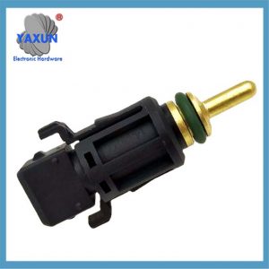
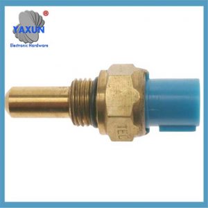
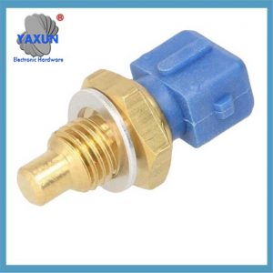
Ο αισθητήρας θερμοκρασίας νερού είναι το συστατικό πυρήνα του συστήματος ψύξης αυτοκινήτου. Το βασικό του συστατικό είναι το θερμίστορ NTC, που είναι εγκατεστημένη στην κυλινδροκεφαλή του κινητήρα ή στο κανάλι νερού. Αυτό το στοιχείο φαίνεται απλό, Αλλά είναι πραγματικά πολύ κρίσιμο για τον έλεγχο του κινητήρα. Θα επηρεάσει άμεσα την προσαρμογή του ECU του ποσού έγχυσης και του χρονισμού ανάφλεξης.
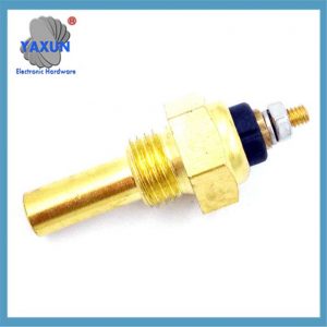
 1433077 13621433077 MEK105210 NSC000100 για συστήματα ψύξης BMW |
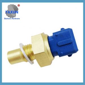
 1/2NPT Water VDO Temperature Sensor for Oil Water Temperature Temp Gauge, 38℃~120℃ |
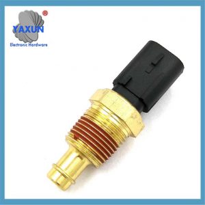
 Αισθητήρας θερμοκρασίας νερού κινητήρα 3/8 NPT 3W 103 ΜΕΡΟΣ ΓΕΝΝΗΣΗ ΑΙΣΘΗΤΗΡΑΣ ΘΕΡΜΟΚΡΑΣΙΑΣ ΜΗΧΑΝΗΣ |
The resistance of the thermistor inside the sensor will change with temperature: the lower the temperature, Όσο μεγαλύτερη είναι η αντίσταση, and the higher the temperature, the smaller the resistance. The ECU determines the water temperature by measuring this resistance change. 8 Supplementary Note: At 30°C, the resistance is usually between 1.4-1.9kΩ.
The installation position of the water temperature sensor varies greatly for different models: Corolla is on the right side of the cylinder block, Accord is on the front of the engine, and Focus is on the rear of the cylinder block. Modern models are more installed on the side of the cylinder head near the thermostat.
Common failure phenomena of water temperature sensors: difficult cold start, ασταθής ταχύτητα ρελαντί, abnormal water temperature gauge, και τα λοιπά. The engine needs to increase the injection amount by 30% at low temperatures, and if the sensor fails, it cannot be compensated correctly.
There are five ways to detect water temperature sensors: multimeter resistance measurement, hot water test, data flow analysis, και τα λοιπά. Μεταξύ αυτών, heating test with a multimeter is the most commonly used on-site detection method.
When replacing the water temperature sensor, the coolant must be drained first, otherwise it will cause air intake in the cooling system. Μετά την εγκατάσταση, the sealing should also be checked to prevent coolant leakage.
 0015422317 A0105422317 0025425917 0005423717 3455427417 Coolant Water Temperature Sensor Switch |
 Honda car sensor thermal switch 37770-PY3-A01 37770PY3A01 |
 Applicable to Daewoo Chevrolet water temperature sensor 96279857 96325864 |
The following is a comprehensive description of the automotive water temperature sensor, which is organized in combination with technical principles, functional characteristics and troubleshooting points:
εγώ. Core structure and working principle
1. Thermistor characteristics
Using negative temperature coefficient (NTC) semiconductor materials, the resistance value decreases exponentially when the temperature rises (about 2.5kΩ at 20℃, and drops to 0.3kΩ at 80℃).
The resistance change is converted into an electrical signal (1.3-3.8V linear range) through a three-wire or four-wire circuit and transmitted to the engine control unit (ECU).
2. Signal output logic
The ECU calculates the water temperature in real time after receiving the voltage signal:
Low temperature conditions (-20℃): Increase the ignition advance angle by 8-12° and increase the injection amount (+30% αποζημίωση ψυχρής εκκίνησης).
High temperature conditions (100℃): Delay the ignition advance angle by 4-6° to prevent explosion.
Ii. Installation location and type
| Location classification | Proportion | Typical model examples |
| Cylinder head/cylinder water jacket | 65% | Toyota Corolla (right side of cylinder block) |
| Water channel near thermostat | 22% | Honda Accord (front of engine) |
| Radiator outlet pipe | 13% | Ford Focus (rear of cylinder block) |
Σημείωμα: Modern models mostly use a four-wire integrated sensor, which is fixed at the thermostat interface on the side of the cylinder head.
III. Detailed explanation of functions and effects
1. Engine control
Fuel correction: increase the injection concentration at low temperature and restore the reference injection amount at high temperature.
Idle speed adjustment: increase the speed to 1200-1500rpm at low temperature (through the idle speed control valve).
2. Cooling system management
When the water temperature is ≥95℃, the cooling fan is triggered to start (coordinated with the normally closed temperature control switch).
When the temperature is abnormally high (>105℃), the fan high-speed operation mode is activated.
3. Instruments and diagnosis
The drive water temperature gauge displays the real-time temperature (σφάλμα <±15℃ is normal).
Output fault code (such as P0115/P0118) for the diagnostic instrument to read.
IV. Fault manifestation and diagnosis
Common fault types
| Fault phenomenon | Root cause | Impact on the engine |
| Difficult cold start | Thermistor open circuit/short circuit | ECU cannot provide rich mixture |
| Idle speed fluctuation/flashing | Signal drift (abnormal resistance value) | Fuel injection correction failure |
| Water temperature gauge abnormal display | Poor line contact or sensor damage | Pointer stuck or indication out of range |
| Fan continues to run | High temperature signal false alarm (such as short circuit to positive pole) | ECU misjudged as overheating |
Diagnostic method
1. Resistance test
Remove the sensor and use a multimeter to measure the resistance between the terminals:
30℃ environment: normal resistance value 1.4-1.9kΩ.
80℃ hot water immersion: resistance should drop to 0.3–0.4kΩ (if unchanged, failure).
2. Data flow analysis
The diagnostic instrument reads the ECU data flow:
Normal value: 90–105℃ (driving).
Fault prompt: Display -40℃ (ανοιχτό κύκλωμα) or 130℃ unchanged (βραχυκύκλωμα).
V. Maintenance precautions
1. Replacement operation specifications
Drain the coolant before removing the sensor to avoid air intake in the cooling system.
Use sealant during installation, and control the torque to 8–12N•m (leakage prevention).
2. Model selection and matching
Resistance range: Need to match the original car’s 275–6500Ω resistance characteristics.
Interface type: Confirm the specifications such as M18×1.5 thread or ZM14 taper thread.
Warning: Sensor failure can cause fuel consumption to increase by more than 15% or permanent damage to the engine, and needs to be replaced in time.
γοργόνα Copy Code
graph TD
ΕΝΑ[Water temperature sensor failure] –> σι{Detection steps}
σι –> ντο[Multimeter resistance measurement]
σι –> ρε[Diagnostic instrument reads data stream]
ντο –>|Abnormal resistance| μι[Αντικαταστήστε τον αισθητήρα]
ρε –>|Signal drift| μι
ντο –>|Normal resistance| φά[Check line grounding]
ρε –>|Normal signal| σολ[Check other systems]